

Technical Data
TD534-0501002U
Instructions for the Installation,
Operation and Maintenance
of W-SLC-7.2
Effective January 2013
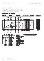
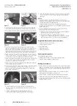
Figure 7
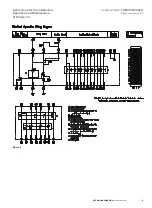
Figure 8
Figure 9
Figure 10
Figure 11
Figure 12
Supplied documents and accessories
• Product qualification certificate
• Factory inspection report
• Instruction Book
• Shipping document
• Schematic diagrams
Ordering information
When ordering, please notify:
• Product type numbers, style numbers and quantities
• For other special requests, please notify
Safety precautions
• Notice: Protect the vacuum interrupter from impact from external
objects. Please follow the instruction book for inspection before
putting into use. Only after it’s confirmed as qualified, the W-SLC
is ready for use.
• Before maintenance, do not conduct any maintenance work
when panels and secondary circles are live.
• Do not conduct maintenance when the contactor is closed.
• Make sure to remove all the tools before operating the unit.
• Lifting lugs shall be removed from the unit and should be stored
properly for back up use.
a) During circuit resistance testing, testing current should not
go through primary disconnect springs;
b) Do not loosen the parts sealed on the frame and
mechanisms. If required for adjustment, please ask trained
staff or manufacturer’s staff to carry out the procedure.
1. In order to prevent unexpected accidents, works such as
adding lubricants to operating mechanisms shall be conducted
with the contactor in the open position
2. Trouble shooting for the W-SLC should be performed by
trained staff or manufacturer’s service people, in order to make
proper adjustments
3. If users need to conduct parameter testing for the W-SLC,
please pay attention to following notices:
3. Use special tool (the part No. is 534-8161200) for assembling
fuse tube to remove movable fuse holder cover, see Figure 8;
4. Put on clean electrician gloves and remove the fuse, see Figure 9;
5. Check the sliding-connecting spring contact fingers on both
ends of fuse holder, to make sure that there is no abnormity or
deformation in the fuse holder. Then add a small amount of
conductive paste evenly on the inner side of each spring contact
finger (the side contacting the fuse), see Figure 10 and Figure 11;
6. Hold a new fuse in hand. Take care to notice that the striker pin
side is facing inwards. After center alignment is confirmed, push
it to the end at a constant speed in a horizontal direction;
7. Mount the head of fuse holder, and use special tool (the part No.
is 534-8161200) to assemble the fuse tube and to fasten the
movable fuse holder cover into position;
8. Mount screws to fasten the movable fuse holder cover and use
inner hexagon spanner to tighten;
9. Use the other end of the special tool (the No. is 534-8161200) to
measure the length by which the fuse is above the fuse unit
base, to make sure that the plane of upper arm is within the
notch range, see Figure 12;
10. Check for abnormity in spares and parts including primary
contact. Check any removed spares and parts which have not
mounted back;
11. Conduct again opening and closing operation tests, to
make sure that operating and interlocking work properly;
12. Rack into the panel once again. Use the cradle racking handle
to rack the W-SLC-7.2 to ‘Service’ position, to be ready for
operation.
Notice:
9
EATON CORPORATION
www.eaton.com


