


11
EATON Vane Motors M-2740-S June 2011
Service, Inspection and Maintenance
Service Tools
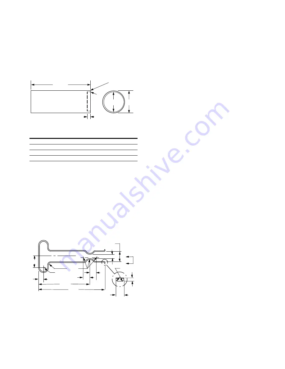
Special tools required for these units are shaft seal drivers
and adapter extractor tool. The seal drivers can be made from
round stock machined as shown in Figure 7.
The recess in the tool will be deep enough so uniform
pressure is applied to the recessed area in the seal channel
rather than on the seal lip. The outside diameter of the tool
will not interfere with the spring around the seal lip.
The adapter extractor tool is designed to remove the hub
adapter from the body after the cartridge is removed (see
Figure 8). The extractor tool engages between the ball
bearing and the hub adapter.
Inspection
Periodic inspection of oil condition and tubing connections
can save time-consuming breakdowns and unnecessary parts
replacement. The following should be checked regularly.
1. All hydraulic connections must be kept tight. A loose
connection in a pressure line will permit the fluid to
leak out. Loose connections in other lines can permit air
to be drawn into the system, resulting in noisy and/or
erratic operation.
2. Clean fluid is the best insurance for long service life.
Therefore, the reservoir should be checked periodically
for dirt or other contaminants. If the fluid becomes
contaminated, the system should be thoroughly drained
and the reservoir cleaned before new fluid is added.
3. Filter elements also should be checked and replaced
periodically. A clogged filter element results in a higher
pressure drop. This can force particles through the filter
which would ordinarily be trapped, or can cause the
bypass to open, resulting in a partial or complete loss of
filtration.
4. Air bubbles in the reservoir can ruin the motor and other
components. If bubbles are seen, locate the source of the
air and seal the leak.
Adding Fluid To The System
When hydraulic fluid is added to replenish the system, it
should always be poured through a fine wire screen (200
mesh or finer).
It is important that the fluid be clean and free of any
substance which could cause improper operation or wear
of the motor or other hydraulic units. Therefore, the use of
cloth to strain the fluid should be avoided to prevent lint from
getting into the system.
Lubrication and Adjustments
Internal lubrication is provided by system oil flow. No periodic
adjustments are required, other than to maintain proper shaft
alignment with the driving medium.
Replacement Parts
Reliable operation throughout the specified operating range is
assured only if genuine Vickers parts are used. Part numbers
are shown in the parts drawings listed in Table 1.
Product Life
The longevity of these products is dependent upon
environment, duty cycle, operating parameters and system
cleanliness. Since these parameters vary from application to
application, the ultimate user must determine and establish
the periodic maintenance required to maximize life and
detect potential component failure.
Troubleshooting
Table 5 lists the common difficulties experienced with vane
motors and hydraulic systems. It also indicates the probable
causes and remedies for each of the troubles listed.
It should always be remembered that many apparent motor
failures are actually due to the failure of other parts of the
system. The cause of improper operation is best diagnosed
with adequate testing equipment and a thorough understand-
ing of the complete hydraulic system.
5.000
A
C
B
Radius Blend
Figure 7.
Figure 8.
Z
Z
.12R
1.38
.63
.19
.38
8.50
6.56
.63
.81
Adapter Extractor Tool
(14 gauge – SAE 1040 stock)
.50 R
.56 R
.81
1.00
5.000
A
C
B
Radius Blend
Figure 7.
Figure 8.
Z
Z
.12R
1.38
.63
.19
.38
8.50
6.56
.63
.81
Adapter Extractor Tool
(14 gauge – SAE 1040 stock)
.50 R
.56 R
.81
1.00
Dimension
Motor Size
A
B
C
25M-20
.312 1.375 1.468
35M-20
.312 1.687 1.781
45M-20
.437 1.906 2.218
50M-20
.437 2.166 2.348
NOTE: All dimensions in inches