background image

EMP-A-11

TB2-*

Load Neg. Out

Load Pos. Out

Volt-Ohm Meter (VOM)

Servo Coil

20

Remove signal
wiring at
terminals 4 & 5.

Symbolize the wires 
removed to prevent error.

Common ground

Input signal

Test Potentiometer

5000 Ohm Linear
Potentiometer

Note

If the EMP-A-11 power supply is not used,
connect the power source as shown to
test the EM-A-11 amplifier.

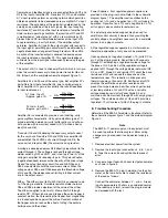
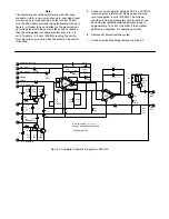
Figure 4. Test Potentiometer Wiring Diagram

1

2

3

4

5

6

7

8

+DC

–DC

Summary of Contents for Vickers EM-A-10

Page 1: ...Revised 09 01 87 I 3081 S Single Ended Linear DC Servo Amplifier EM A 10 Vickers Servo Valves Service Data ...

Page 2: ...ble 1 for electrical and mechanical specifications C Installation The EM A 10 servo amplifier is designed for mounting on a power supply plate such as the EMP A 11 Input and output connections to the amplifier circuitry are provided by printed circuit pin connections on the module These pin connections when installed into a plug in receptacle must be connected as shown in Table 2 TB2 wiring interc...

Page 3: ... circuit Dither The dither signal 60 to 400 Hertz is connected to pin 1 of the plug in module A variable resistive divider network R16 and R18 provide adjustment of the value of the dither The dither is applied to pin two 2 of amplifier A2 through resistor R17 Dither signal is used to keep the servo flapper in constant motion thus preventing the flapper from magnetizing in a locked condition again...

Page 4: ... 0 volts at one end of the test potentiometer adjustment range to approximately 1 5 volts at the other If the amplifier performs as indicated it is operating normally 6 Remove AC power from the system 7 Connect symbolized wiring removed in step E 2 12 11 6 5 7 4 8 3 2 1 3 8 15 7 13 1 2 5 4 6 D C Supply In R15 R13 2 2K R11 Z2 Q4 Q2 D 2 2 7K R7 1 5 K Z 4 Z 6 Z 5 Supply Out R9 1 5 K R6 Supply Out 2 7...

Page 5: ...gram of the EM A 10 Figure 3 Simplified Schematic Diagram of the EM A 10 10 Vdc R16 22K R17 22K DITHER R18 1K R20a R20 82K 50K R1 R2 5K A1 A2 R21 3 3K 10 1 INV 4 5 R4 200K R3 10K R23 3 3K 12 15 R26 3 Ω Load 11 Factory Adjust ...

Page 6: ...nals 4 5 Symbolize the wires removed to prevent error Common ground Input signal Test Potentiometer 5000 Ohm Linear Potentiometer Note If the EMP A 11 power supply is not used connect the power source as shown to test the EM A 11 amplifier Figure 4 Test Potentiometer Wiring Diagram 1 2 3 4 5 6 7 8 DC DC ...

Reviews: