13
Instruction Booklet
IB02201004E
Effective October 2017
Revision #4
Instructions for installation, operation, and
maintenance of 38 kV type VacClad-W,
150 BIL switchgear indoor housings
EATON
www.eaton.com
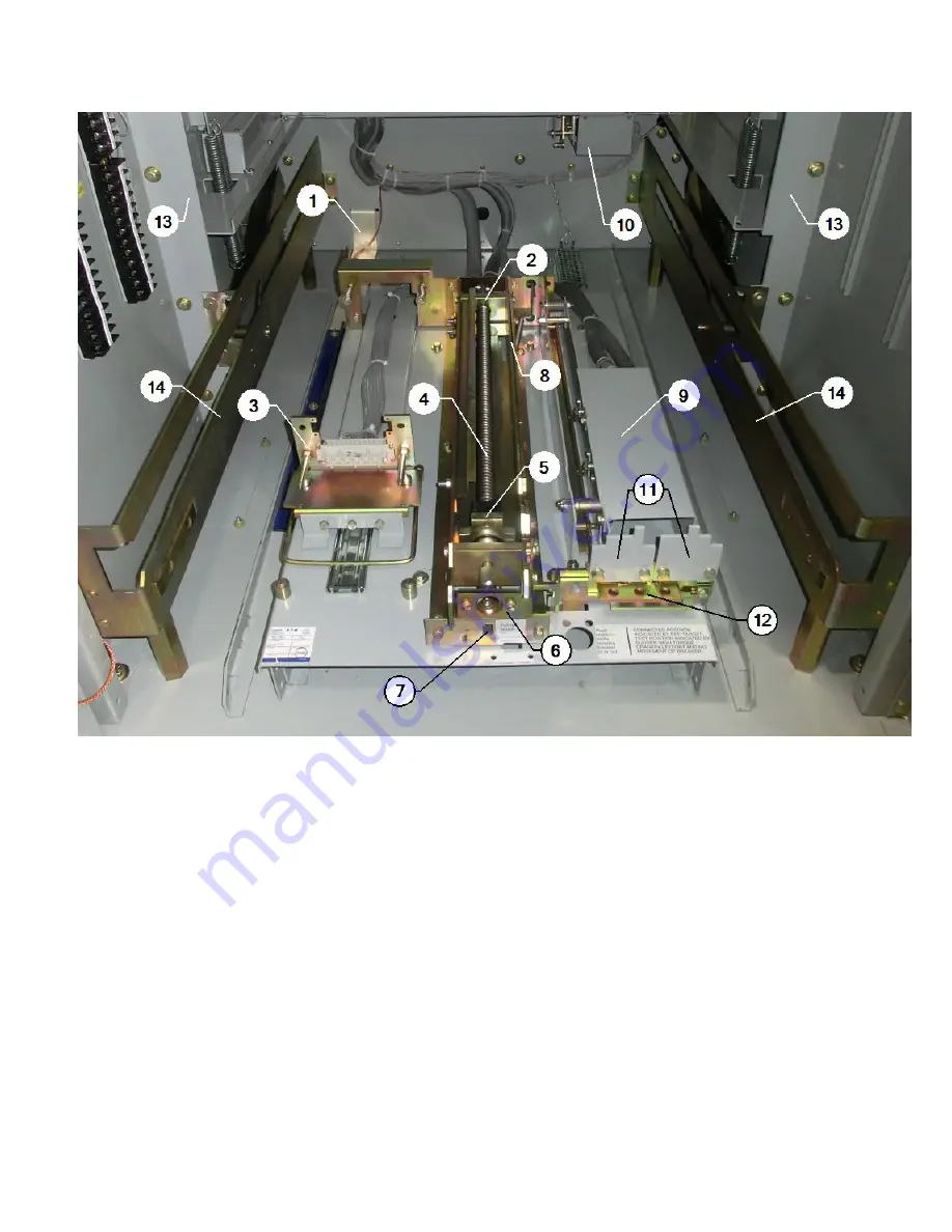
Figure 15. Pan Assembly.
3.2 Breaker pan assembly
1 . Grounding contact grounds the breaker in all positions .
2 . The levering system prevents removal of the breaker in any posi-
tion other than the Disconnect (or Test) position .
3 . Secondary disconnect assembly – Consists of a secondary plug
handle, slider assembly, secondary plug, and control wires . The
control wiring is arranged for pullout disconnecting by means of
a female receptacle (secondary plug) arranged to connect to a
male plug on the breaker . The secondary disconnect is the
connection for the control leads between the removable breaker
and the stationary housing (see the breaker Instructional Booklet
IB3A74792 for more description) .
4 . Racking screw performs breaker insertion and withdrawal .
5 . Moving block couples to breaker for insertion and withdrawal .
6 . Slider is used with #8 to prevent levering a closed breaker . May
also be used in conjunction with #12 to padlock a breaker in
either position .
7 . Indicates when the breaker is in the fully connected position .
Represents positive indication of the breaker in the Connect posi-
tion by use of a red flag that rotates into viewing position when
the breaker is fully connected .
8 . Slider interlocks prevent removing a closed breaker .
9 . The mechanism operated cell (MOC) switch is an assembly of
switches that is operated by a lever on the breaker mechanism .
Refer to the shop order drawings for the number of NO and NC
contacts provided . The MOC switch is activated by the breaker
closing . It extends a lever out the bottom of the breaker mecha-
nism pushing down on the lever of the operating mechanism on
the MOC assembly . This, in turn, transmits the motion to oper-
ate the switch .
10 . The truck operated cell (TOC) switch has nine poles . Four con-
tacts make and five contacts break as the breaker is levered to
the Connected position . As the breaker is being levered into
the Connect position, a bracket on the breaker pushes the TOC
switch lever during the last inch of travel . As a result, the TOC
switch can be used to electrically indicate whether or not the
breaker is in the Connect position .
11 . Coding plates – See Safety features .
12 . Optional provision for padlocking (up to three locks) a breaker in
any position .
13 . Metal framework provides a closed barrier to the primary com-
partment when the breaker is connected .
14 . Rail on which the breaker rolls .


