background image

5

Standard Installation

Note:

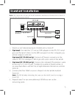
 The diagram below shows a B119-2X2 installation. Installation will be the same for the B119-

4X4, except for the number of ports.

B119-2x2

(Optional)

Up to 25 ft.

Up to 16 ft.

Up to 16 ft.

Up to 25 ft.

Blu-Ray™

1.  Make sure all devices being connected are turned off.

2. 

Optional:

 Connect the 3.5 mm to DB9 adapter to the RS-232 serial 

port on the switch, then to the DB9 serial port on the computer you 

will be using to control it.


Optional (B119-4X4 only): 

Connect a Phoenix connector to the 

switch’s RS-232 serial port, which you will use to control the switch.

3. 

Optional (B119-4X4 only): 

Connect the included IR extension cable 

to the unit’s 3.5 mm IR jack. Position the cable’s infrared sensor in 

an area that allows a direct line of sight between the sensor and the 

remote.

4. 

Connect the first HDMI source to the port on the switch marked 

Source A


Note: 

The HDMI cable connecting the source to the switch must be no longer 

than 16 ft.

5.  Repeat step 3 to connect additional HDMI sources to the  

remaining ports.

Summary of Contents for TRIPP LITE B119-2X2

Page 1: ...Mounting 4 Standard Installation 5 RS 232 Serial Control For B119 2X2 7 RS 232 Serial Control For B119 4X4 11 Troubleshooting 14 Warranty 16 Owner s Manual Purchased product may differ from image Mode...

Page 2: ...to DB9 Adapter Cable Remote Control Mounting Hardware Owner s Manual B119 4X4 Local Transmitter External Power Supply Input 100 240V 50 60 Hz 0 6A Output 5V 3A 4 International Plug Adapters North Ame...

Page 3: ...nt of the matrix switch and maintain device switching functionality with the included 5 ft IR extension cable Monitors can be located up to 25 ft from the switch Supports video resolutions up to 1080p...

Page 4: ...ety of ways The following images show the different ways the included mounting brackets can be attached Note The images below show a B126 1A1 HDMI over Cat5 Receiver Unit but the mounting hardware ins...

Page 5: ...uter you will be using to control it Optional B119 4X4 only Connect a Phoenix connector to the switch s RS 232 serial port which you will use to control the switch 3 Optional B119 4X4 only Connect the...

Page 6: ...5 ft 8 Repeat step 7 to connect additional displays to the remaining ports 9 Turn on the power to the connected devices The video image should now be displayed on the connected monitors 10 Press the s...

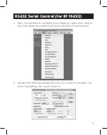
Page 7: ...l Control For B119 2X2 Before using RS 232 Serial Control you must first go into your Terminal Emulation Software and update the COM port settings 1 Go to the Setup drop down menu and select the Seria...

Page 8: ...the remaining settings as follows Baud Rate 57600 or 9600 Data 8 bit Parity none Stop 1 bit Flow Control none Note The baud rate in the below image lists 57600 if 57600 does not work this value should...

Page 9: ...3 Next you will need to configure your software to allow input control Go to the Setup drop down menu and select the Terminal option 4 Update the following settings Receive LF Local Echo enable The re...

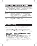
Page 10: ...llowing table lists the available commands Command Action sw x n Switches the source being displayed on the selected output x is the output 1 2 3 or 4 and n is the desired source A B C or D For exampl...

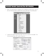
Page 11: ...al Control For B119 4X4 Before using RS 232 Serial Control you must first go into your Terminal Emulation Software and update the COM port settings 1 Go to the Setup drop down menu and select the Seri...

Page 12: ...port that is being used and update the remaining settings as follows Baud Rate 57600 or 9600 Data 8 bit Parity none Stop 1 bit Flow Control none Note The baud rate in the below image lists 57600 if 57...

Page 13: ...3 Next you will need to configure your software to allow input control Go to the Setup drop down menu and select the Terminal option 4 Update the following settings Receive LF Local Echo enable The re...

Page 14: ...les that can support the video resolution you are trying to obtain It is recommended that you use P568 Series High Speed HDMI cables as they have been tested to work with the B119 Series Matrix Switch...

Page 15: ...o longer than 16 ft in length The 24 AWG HDMI cable connecting the switch to a display must be no longer than 25 ft in length 7 If you are having trouble getting your Terminal Emulation Software to re...

Page 16: ...Class B This device complies with part 15 of the FCC Rules Operation is subject to the following two conditions 1 This device may not cause harmful interference and 2 this device must accept any inte...

Page 17: ...cling on a one for one like for like basis this varies depending on the country Send the new equipment back for recycling when this ultimately becomes waste WARNING Use of this equipment in life suppo...

Page 18: ...18...

Page 19: ...19...

Page 20: ...evard Cleveland OH 44122 United States Eaton com 2024 Eaton All Rights Reserved Publication No 23 12 116 93 32BC_RevG January 2024 Eaton is a registered trademark All trademarks are property of their...

Reviews: