background image


15 

www.eaton.com/wireless


call toll free: 1-800-663-8806


DMAN-4077-01   R01


Service Mode:  Modify RCU time out 

RCU Timeout 

As a battery saving feature the RCU has the ability to turn it self off after a 

defined period of inactivity. 

The RCU timeout is configurable from 1 to 998 minutes in 1 minute incre-

ments.  A value of 0, the default value, disables the RCU timeout. 

To adjust the RCU timeout press button 

.   T 

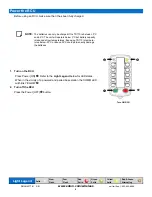
10 user buttons represent numeric values from 1-9 as shown on the picture 

left. LEDs on the 10 user buttons will flash RED to display the current user 

settings.   

First RED flash represent the 100’s figure of RCU timeout. The second 

RED flash represent the 10’s figure of RCU timeout. The third RED flash 

represent the 1’s figure of  RCU timeout.  

For example, a time out of 138 minutes is displayed as below. 


Press three buttons in sequence to set the timeout. First button represent 

100’s , second button represent 10’s, and third button represent 1’s figure 

of RCU timeout. When each button is pressed, corresponding button LED 

will turn on GREEN momentarily.  LEDs will display the new value once the 

button sequence is complete. 

Press and release Power ON [GREEN] to save your changes.  Press and 

release Power OFF [RED] to abort any changes and turn off unit. 

CAUTION:

  When a RCU turns off due to inactivity it will cause the base station it is communicating with to 

go in to its safe state.  The base station safe state by default is all functions off unless specified 

differently by your equipment supplier. 

You must be aware of any behavior that may change due to adjusting the timeout and 

consider all safety aspects of operation.  Consult with the supplier of your equipment if 

your are unsure of affected safety operation. 

Failure to follow SAFETY PRECAUTIONS may result in equipment failure and/or serious 

personal injury. 

5 6 

7 8 

3 4 

1 2 

9 0 



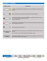
Light Legend  

Solid 

Slow  

Flash 

Fast  

Flash 

Red  

Solid 

Green  

Solid 

Red & Green 

Alternating 

Yellow 

Solid 

5 6 

7 8 

3 4 

1 2 

9 0 

5 6 

7 8 

3 4 

1 2 

9 0 

5 6 

7 8 

3 4 

1 2 

9 0 

5 6 

7 8 

3 4 

1 2 

9 0 

Summary of Contents for TD110 RCU

Page 1: ...06 DMAN 4077 01 R01 TD110 RCU Installation Configuration Manual EATON DBA Cooper Industries Electrical Inc 74 1833 Coast Meridian Road Port Coquitlam BC Canada V3C 6G5 Tel 604 944 9247 Fax 604 944 926...

Page 2: ...l rights title and interest in and to without limitation all intellectual and proprietary rights of any and all featured products or parts including but not limited to any models data or formulas exhi...

Page 3: ...nization and layout are copyright protected under United States and international copyright laws Any Eaton Content protected by intellectual property laws may not be copied republished posted modified...

Page 4: ...e Mode Modify RCU timeout 13 Service Mode Run Diagnostics 16 Operations TD110 RCU 17 Operations Charge Cradle 18 Troubleshooting Guide 20 Notes 23 Parts Accessories 24 Specifications 24 Warranty Infor...

Page 5: ...t concrete etc from the unit to prevent clogging of buttons etc by using a damp cloth Maintenance Welding DISCONNECT THE BASE STATION FROM THE MACHINE BEFORE WELDING Failure to disconnect will result...

Page 6: ...prohibited Lithium Ion batteries are subject to disposal and recycling regulations that vary by country and region Always check and follow your applicable regulations before disposing of any battery C...

Page 7: ...ase station within a metal box with a securable door or hatch Secure the box using a key preferably of a type that is not widely circulated nor easily duplicated Run all cabling through industry stand...

Page 8: ...hniques enables our industrially hardened FHSS signals to overcome interference that commonly affects licensed radios The 12 button TD110 provides the user flexibility to control the functions they ne...

Page 9: ...tation the COMM LED will blink YELLOW 2 Turn off the RCU Press the Power OFF button Power the RCU NOTE The batteries can only be charged if the TD110 is between 0 C and 45 C The unit will operate belo...

Page 10: ...on on the RCU including the Power button will restart the timeout monitoring Follow these steps to ensure that there is a radio link between the RCU and Base Station Refer to the Light Leg end below f...

Page 11: ...rned ON then immediately proceed to next step C Release Power OFF RED D Release Power ON GREEN The COMM LED will blink YELLOW when unit enters service mode If no buttons are pressed within 5 minutes a...

Page 12: ...Prepare the TD110 Make sure TD110 is in service mode Do not yet press the Power ON GREEN button NOTE It is necessary to associate the RCU to base station when replacing either the RCU or base station...

Page 13: ...ds the base station will time out The Status light stays solid green and E Stop light will slowly flash red after Setup Mode has timed out To return to Setup Mode repeat step 2 2 Light Legend Solid Sl...

Page 14: ...iring will start and the COMM LED on TD110 will turn on YELLOW B NOTE If the pairing fails the TD110 STATUS LED will turn ON RED Correct any errors cycle power to both the RCU and base station then re...

Page 15: ...sent 10 s and third button represent 1 s figure of RCU timeout When each button is pressed corresponding button LED will turn on GREEN momentarily LEDs will display the new value once the button seque...

Page 16: ...r 1 On the TD110 press top right Button to enter Diagnostic mode 2 STATUS LED will blink RED and GREEN All LEDs will turn on RED 3 Press each button to test On each button press the associated but ton...

Page 17: ...from 1 9 as shown on the picture left First RED flash represents the most significant digit of the software build version The second RED flash represents the second digit from the left and so on For...

Page 18: ...nal error is preventing the RCU from operating When available a specific error mes sage is displayed on the screen Out of range vibrate notification When the RCU moves out of radio range of the base s...

Page 19: ...7 RLY COM RCU Present Relay common 8 PARK IN Vehicle in Park input when 6V RCU Present Outputs Connections 5 8 can be used to wire to an indicator to alert the vehicle operator if the RCU is not place...

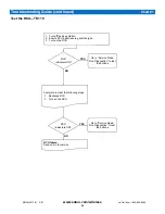
Page 20: ...base station 2 Ensure RCU batteries are good charged 3 Turn on the RCU Go to Service Mode Run Diagnostics to test the buttons RCU indicators ON NO YES Complete in order the following steps 1 Recharge...

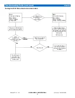
Page 21: ...e the unit functions correctly If not proceed to Chart 1 The RCU code may need to be paired to the base station again Troubleshooting Guide continued Chart 2 RCU Active light is flashing Base station...

Page 22: ...e there are 2 symptoms to look for 1 The Link light on the base station will not turn GREEN when the power switch is toggled on the RCU to download 2 The base station will time out indicating that it...

Page 23: ...23 www eaton com wireless call toll free 1 800 663 8806 DMAN 4077 01 R01 Notes...

Page 24: ...shall have no responsibility to repair or replace the product under warranty In no event shall EATON be responsible for incidental or consequential damage caused by defects in its products whether suc...

Reviews: