background image

4 CANopen communication settings

4.7 Parameters

40

CANopen for DA1, DC1, DE11

09/16 MN040019EN

www.eaton.com

4.7 Parameters

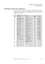
The following tables show the CANopen parameters on the variable 
frequency drive/variable speed starter.

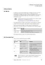
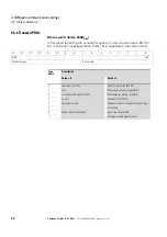
The abbreviations and acronyms used in the table are defined below:

Abbreviation

Significance

CANopen Index

The parameter‘s identification number in CANopen (identification number)

RUN

The parameter can be accessed during operation (Run signal)

STOP

The parameter can only be accessed in STOP mode

ro/rw

Parameter read and write permissions:
ro = read only
rw = read and write

Designation

Name of parameter

Value

• Setting value of the parameter
• value range
• Display value

DS

Default setting (the parameter's value when using the device‘s factory settings)
The values in parentheses are the default settings when using a frequency of 60 Hz.

Page

The page number in this manual containing a detailed description of the parameter.

Summary of Contents for PowerXL DA1

Page 1: ...Manual PowerXL CANopen Communication Manual for Variable Frequency Drives Variable Speed Starters DA1 DC1 DE11 09 16 MN040019EN ...

Page 2: ...86 2273 option 2 option 6 8 00 a m 5 00 p m Central Time U S UTC 6 email TRCDrives Eaton com www eaton com drives Original Operating Instructions The German language edition of this document is the original operating manual Translation of the original operating manual All editions of this document other than those in German language are translations of the original German manual 1st published 2016...

Page 3: ...e dip or failure This should not cause dangerous operating states even for a short time If necessary emergency stop devices should be implemented Wherever faults in the automation system may cause injury or material damage external measures must be implemented to ensure a safe operating state in the event of a fault or malfunction for example by means of separate limit switches mechanical interloc...

Page 4: ...II ...

Page 5: ...on resistor 13 2 3 2 Baud rate 14 3 Commissioning 15 3 1 Hardware enable signal 15 4 CANopen communication settings 17 4 1 Parameters that need to be configured on DA1 devices 17 4 2 Parameters that need to be configured on DC1 devices 19 4 3 Parameters that need to be configured on DE11 devices 20 4 4 Configuration of the control signal terminals 21 4 4 1 Control signal terminal configuration for...

Page 6: ...r specific objects on DC1 E1 devices 36 4 5 10 Manufacturer specific objects on DE11 devices 37 4 6 Fault messages 38 4 7 Parameters 40 4 7 1 Parameters on DA1 devices 41 4 7 2 Parameters on DC1 devices 50 4 7 3 Parameters on DC1 E1 devices 52 4 7 4 Parameters on DE11 devices 58 5 Application example CANopen fieldbus connection on DA1 variable frequency drives 61 5 1 Setting up the PLC 61 5 2 Mate...

Page 7: ...ith how to operate DA1 DC1 variable frequency drives and or DE11 variable speed starters as applicable Please read this manual carefully before commissioning a CANopen network connection We assume that you have a good knowledge of engineering fundamentals and that you are familiar with handling electrical systems and machines as well as with reading technical drawings 0 2 List of revisions The fol...

Page 8: ... Indicates instructions to be followed 0 3 1 Hazard warnings of material damages 0 3 2 Hazard warnings of personal injury Indicates useful tips and More Info NOTICE Warns about the possibility of material damage CAUTION Warns of the possibility of hazardous situations that may possibly cause slight injury DANGER Warns of hazardous situations that result in serious injury or death ...

Page 9: ...ion delays and connection problems into account Carefully and individually test every implementation of a product before putting it into operation Observe all general accident prevention and local safety regulations Information for the USA For more information please refer to the latest issue of NEMA ICS 1 1 Safety Guidelines for the Application Installation and Maintenance of Solid State Control ...

Page 10: ...uction leaflet IL04020013Z for devices with an IP66 degree of protection For DE1 variable speed starter Instruction leaflet IL040005ZU These documents are available as PDF files on the Eaton Internet website http www eaton de EN EatonDE ProdukteundLoesungen Electrical Kundensupport index htm Customer support Download Center Documentation In the Quick Search box enter the document number IL04020010...

Page 11: ...on on the devices described here can be found on the Internet under www eaton eu powerxl as well as www eaton eu documentation Note on naming convention used throughout the program Throughout this manual the term variable frequency drive is used to refer both to DA1 and DC1 devices and to DE11 variable speed starters ...

Page 12: ...ommunication Object Identifier CONST Constant variable read access only DS Default settings EDS Electronic Data Sheets EMCY Emergency Object HEX Hexadecimal base 16 numeral system ID Identifier PC Personal Computer PDO Process Data Object ro Read Only read access only ROM Read Only Memory rw Read Write read write access Rx Receive SDO Service Data Object Tx Transmit Designation US American value U...

Page 13: ...ss data objects PDOs and service data objects SDOs The variable frequency drive is controlled with fast cyclic process data PDOs The process data channel can be used not only to specify the speed setpoint but also to trigger various drive functions such as enables operating directions and resets At the same time it can also be used to read actual values such as the actual speed current and device ...

Page 14: ...epeater Total distance depending on the baud rate the repeater up to 500 m at 125 kBit s up to 300 m at 1 MBit s Transmission medium Screened twisted pair cable Bus termination resistor EASY NT R 120 Ω suitable for separate mounting Number of SDOs 1 server 0 clients Number of PDOs 2 Rx PDO 2 Tx PDO Note Only one of each will be enabled by default PDO mapping Variable Terminal type Plug in RJ45 con...

Page 15: ...interface s location will depend on the specific device model and the variable frequency drive s frame size For more detailed information on where the RJ45 interface is located please refer to the instruction leaflet corresponding to the relevant variable frequency drive CAN_L 1 CAN_H 2 0 V 3 OP Bus_L 4 OP Bus_H 5 24 V 6 Modbus RTU_L 7 Modbus RTU_H 8 DC1 DE1 DA1 L1 L L2 N L3 DC U DC BR 1 2 3 4 5 6...

Page 16: ... control signal and field bus cables and energy carrying mains and motor cables must be greater than 30 cm Cables should always intersect at right angles Figure 3 Routing cables for CANopen and mains motor cables If the system requires a parallel routing in cable ducts a partition must be installed between the fieldbus cable and the mains and motor cable in order to prevent electromagnetic interfe...

Page 17: ...cal end last module of the network cable in order to prevent signal reflections and the associated transfer errors Figure 5 Configuration of the RJ45 interface 2 3 1 Bus termination resistor The first and last modules on a CANopen network must be terminated with a 120 Ω bus termination resistor This resistor needs to be connected between CAN_L and CAN_H To do this you can plug the EASY NT R bus te...

Page 18: ...ication modules on the CANopen bus A value between 125 and 1000 kBit s can be selected for the variable frequency drives baud rate The maximum cable length will depend on the baud rate you use Table 5 Maximum cable length and baud rate Baud rate Maximum cable length 125 kbit s 500 m 250 kBit s M 250 500 kBit s default setting 100 m 800 kBit s 50 m 1000 kBit s 30 m ...

Page 19: ...ck the settings and installations for the connection to the CANopen network which are described in this manual NOTICE Make sure that starting the motor will not put anyone or anything in danger Disconnect the driven machine if there is a danger in an incorrect operating state L Figure 7 Hardware enable left DA1 center DC1 right DE11 By default DC1 variable frequency drives and DE11 variable speed ...

Page 20: ...3 Commissioning 3 1 Hardware enable signal 16 CANopen for DA1 DC1 DE11 09 16 MN040019EN www eaton com ...

Page 21: ... digital reference via internal or remote Keypad or terminals Pressing the keypad START button toggles between forward and reverse 3 PID controller The output frequency will be controlled by the internal PID controller 4 Fieldbus Control Control via Modbus RTU if no fieldbus option is present otherwise control from the fieldbus option module 5 Slave Mode The Variable Frequency Drive acts as a slav...

Page 22: ...int value and the control word will be set via CANopen The ramp times will be set with parameters P1 03 and P1 04 P5 07 1 With the exception of the ramp times the DA1 variable frequency drive will behave the same way as with P5 07 0 The ramp times will be transmitted cyclically By default the ramp time will be third word in the first receive PDO The value will be scaled by a factor of 0 01 Example...

Page 23: ...ol Control via Modbus RTU communication 4 Modbus Control Ramp times via Modbus 5 PI controller with external actual value 6 PI controllerwithexternalactual valueandtotalized value of AI1 7 CANOpen internal ramp times 8 CANOpen CANOpen ramp times 9 SmartWire Device Control and speed ref 10 SmartWire Device Control and terminal speed ref 11 Terminal Control and SmartWire Device speed ref 13 SmartWir...

Page 24: ... between forward and reverse 3 Modbus Control Control via Modbus RTU communication 4 CANopen 5 Reserved 6 Reserved 7 Reserved 8 Reserved 9 SmartWire Device Control and speed ref 10 SmartWire Device Control and terminal speed ref 11 Terminal Control and SmartWire Device speed ref 13 SmartWire DT control setpoint value setpoint enable signal via terminal 0 P 34 162 RUN rw PDP Address 1 63 PDP Addres...

Page 25: ...V is additionally required for starting If ENA is removed the drive will coast EXTFLT Ext Fault Warning FWD Used to start the drive in the forward direction FWD Forward INV Change of rotation INV Inverse The operating direction will be reversed as per the configured ramps High invert Low Do not invert Pulse FWD NO Pulse REV NO Pulse STOP NC Pulse control REV Used to start the drive in the reverse ...

Page 26: ...troller s output High Fixed frequency The fixed frequency itself is selected with the Select f Fix Bit0 Select f Fix Bit1 Select f Fix Bit2 commands Select PID REF f Fix1 DA1 only Used to select between setpoint values Low Setpoint from the PID controller s output High f Fix1 set with P2 01 Select Quick dec DA1 only Used to activate a quick stop with the ramp set with P2 25 In order to activate th...

Page 27: ...nction Select f Fix Bit0 2 ENA INV Select f Fix Bit0 Select f Fix Bit1 Select f Fix Bit2 3 ENA INV Select BUS REF f Fix1 No function AI2 Torque REF 4 ENA INV Select BUS REF f Fix1 No function Select t dec t dec2 5 ENA INV Select BUS REF AI2 REF No function AI2 REF 6 ENA INV Select BUS REF f Fix1 No function EXTFLT 7 ENA INV Select f Fix Bit0 Select f Fix Bit1 EXTFLT 8 ENA INV Select f Fix Bit0 Sel...

Page 28: ...ation for DC1 P 15 DI1 terminal 2 DI2 terminal 3 DI3 AI2 terminal 4 DI4 AI1 terminal 6 0 START No function No function No function 1 Not permissible 2 Not permissible 3 START Select BUS REF f Fix1 EXTFLT No function 4 Not permissible 5 Not permissible 6 START Select BUS REF AI1 REF EXTFLT AI1 REF 7 START Select BUS REF DIG REF EXTFLT No function 8 Not permissible 9 Not permissible 10 Not permissib...

Page 29: ...nction No function 1 Not permissible 2 Not permissible 3 START Select BUS REF f Fix1 EXTFLT No function 4 Not permissible 5 Not permissible 6 START Select BUS REF AI1 REF EXTFLT AI1 REF 7 START Select BUS REF DIG REF EXTFLT No function 8 Not permissible 9 Not permissible 10 Not permissible 11 Not permissible 12 Not permissible 13 START No function EXTFLT No function 14 Not permissible 15 FWD Selec...

Page 30: ...FF1 DOWN 51 ENA UP EXTFLT DOWN 61 ENA ENADIR UP DOWN 7 ENA FF20 EXTFLT FF21 8 ENA DIR FF1 n F 9 ENA DIR EXTFLT n F 1 P 15 4 5 and 6 requires an enable signal start command via CANopen and at DI1 Digital reference values sent via CANopen will be ignored in this case It will only be possible to use UP and DOWN to set a setpoint value n F No function When configured this way the control terminals n F...

Page 31: ... options available Table 15 CANopen transmission options To get the latest version of the EDS file for your device please download it from the Eaton FTP server https es assets eaton com DRIVES POWERXL 04_CANopen Range Description 00 00hex 1F FFhex Communication specific objects from DS 301 20 00hex 5F FFhex Manufacturer specific objects the variable frequency drive s parameters Transmission Type M...

Page 32: ...ge rw 80 UNSIGNED32 1008 00 Manufacturer Device Name The variable frequency drive s device name DA1 ro DA1 STRING 1009 00 Manufacturer Hardware Version Hardware version of the module ro 1 11 Example STRING A 100 00 Manufacturer Software Version Software version of the module ro 1 00 Example STRING C 100 00 Guard Time Monitoring time in milliseconds rw 0000hex Resolution in 1 ms UNSIGNED16 100D 00 ...

Page 33: ...Significance Access right DS Data type 1400 1401 1st Receive PDO Parameter 2nd Receive PDO Parameter Number of valid subindexes ro 03 RECORD 00 Number of Entries Maximum number of entries ro 02 UNSIGNED8 01 PDO COB ID COB ID of 1st Rx PDO COB ID of 2nd Rx PDO rw 4000002 00 400000300 Node ID UNSIGNED32 02 Transmission Type PDO transmission type asynchronous rw 254 UNSIGNED8 1600 00 Number of Mapped...

Page 34: ... ID UNSIGNED32 02 Transmission Type PDO transmission type asynchronous rw 254 UNSIGNED8 03 Inhibit time 100 μs ro 0 UNSIGNED16 1A00 1st Transmit PDO Mapping applies for Tx PDO 1 RECORD 00 Number of Mapped Application Objects Highest subindex used rw 4 UNSIGNED8 01 1st Mapping Object rw 200A0010 UNSIGNED32 02 2nd Mapping Object rw 200B0010 UNSIGNED32 03 3rd Mapping Object rw 200D0010 UNSIGNED32 04 ...

Page 35: ... 258dez 25 8 Hz Torque Reference Index 2002hex DA1 only The Torque Reference is specified as a percentage with one decimal place Example 127dez 12 7 User ramp time Index 2003hex The user ramp time is specified in seconds with two decimal places Type name Description Value 0 Value 1 0 Stop Operational 1 Clockwise rotating field FWD Anticlockwise rotating field REV 2 No action Reset Fault 3 No actio...

Page 36: ...pecified in the status word 15 14 13 12 11 10 9 8 7 6 5 4 3 2 1 0 MSB LSB Fault messages Status word Type name Description Value 0 Value 1 0 Operation not ready Ready for operation READY 1 Stop Running operation message RUN 2 Clockwise rotating field FWD Anticlockwise rotating field REV 3 no error Fault detected FAULT 4 Acceleration ramp Frequency actual value equals setpoint input 5 Zero speed 6 ...

Page 37: ...current Motor Current ro UNSIGNED16 200E Motor Torque Torque ro INTEGER16 200F Motor power Power in kW ro UNSIGNED16 2010 Drive temperature Variable frequency drive temperature ro INTEGER16 2011 DC bus value DC Link Voltage ro UNSIGNED16 2012 Digital input status State of digital inputs ro UNSIGNED16 2013 Analog input 1 Analog input 1 in ro UNSIGNED16 2014 Analog input 2 Analog input 2 in ro UNSIG...

Page 38: ...35 User relay output 3 User relay output 3 rw UNSIGNED16 2036 User relay output 4 User relay output 4 rw UNSIGNED16 2037 User relay output 5 User relay output 5 rw UNSIGNED16 203 A Kilowatt hours Operating time in kW ro UNSIGNED16 203B Megawatt hours Operating time in MW ro UNSIGNED16 203C KWh meter Total operating time in kW ro UNSIGNED16 203D MWh meter Total operating time in MW ro UNSIGNED16 20...

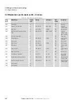
Page 39: ...time rw UNSIGNED16 200 A Drive status register status word ro UNSIGNED16 200B Motor speed Hz Actual value in Hertz Hz ro UNSIGNED16 200D Motor current Motor Current ro UNSIGNED16 2010 Drive temperature variable frequency drive temperature ro Integer 16 2011 DC bus value DC Link Voltage ro UNSIGNED16 2012 Digital input status State of digital inputs ro UNSIGNED16 2013 Analog input 1 Analog input 1 ...

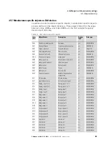
Page 40: ...ference value high resolution 200 A Error code Drive Status ro U16 status word 200B Output Frequency ro 500 50 0 Hz 0 5000 S16 Actual value in Hertz Hz 200D Motor current ro 100 10 0 A U16 Motor Current 200E Motor Torque ro 500 50 0 0 2000 S16 Motor Torque 200F Motor Power ro 100 1 00 kW U16 Instance Motor Power 2015 Analog Output ro 500 50 0 0 1000 U16 Analog output as a 2017 Relay Output Status ...

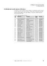
Page 41: ...er Status word ro UNSIGNED16 200B Motor speed Hz Actual value in Hertz Hz ro UNSIGNED16 200D Motor current Motor Current ro UNSIGNED16 2010 Drive temperature Variable frequency drive temperature ro Integer 16 2011 DC bus value DC Link Voltage ro UNSIGNED16 2012 Digital input status State of digital inputs ro UNSIGNED16 2013 Analog input 1 Analog input 1 in ro UNSIGNED16 2014 Analog input 2 Analog ...

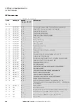
Page 42: ...DE1 P LOss Incoming power phase failure only for devices with a three phase power supply 15 0F DA1 DE1 h O I Overcurrent at output DC1 motor pick up control fault 16 0A DA1 DC1 DE1 Th flt Malfunctioning heat sink thermistor 17 11 DA1 DC1 DE1 dAtA F Error in internal memory 18 12 DA1 DC1 DE1 4 20 F The analog input s input current does not fall within the specified range 19 12 DA1 DC1 E1 dAtA E Err...

Page 43: ...ot connected or has a discontinuity 50 32 DA1 DC1 E1 Sc FO1 No valid Modbus frame was received within the time specified 51 33 DA1 DC1 E1 Sc FO2 No valid CANopen frame was received within the specified time 52 34 DA1 Sc FO3 Communications between the device and the plugged in field bus option have dropped out 53 35 DA1 Sc F04 Communications between the device and the plugged in I O expansion have ...

Page 44: ...er in CANopen identification number RUN The parameter can be accessed during operation Run signal STOP The parameter can only be accessed in STOP mode ro rw Parameter read and write permissions ro read only rw read and write Designation Name of parameter Value Setting value of the parameter value range Display value DS Default setting the parameter s value when using the device s factory settings ...

Page 45: ...ocessData Source rw STOP 0 13 U16 2071 P1 13 DI Config Select rw STOP 0 21 U16 2072 P1 14 Password rw RUN 0 30000 U16 20C9 P2 01 f Fix1 rw RUN 3000 50 0 Hz P1 02 min 0 Hz 0 rpm P1 01 max 500 0 Hz 30000 rpm U16 20CA P2 02 f Fix2 rw RUN 3000 50 0 Hz P1 02 min 0 Hz 0 rpm P1 01 max 500 0 Hz 30000 rpm U16 20CB P2 03 f Fix3 rw RUN 3000 50 0 Hz P1 02 min 0 Hz 0 rpm P1 01 max 500 0 Hz 30000 rpm U16 20CC P...

Page 46: ... Mode rw RUN 1 0 01 0 0 s 250 s U16 20E4 P2 28 Slave SpeedScalingControl rw RUN 0 3 U16 20E5 P2 29 Slave SpeedScalingFactor rw RUN 1 0 1 500 0 500 0 S16 20E6 P2 30 AI1 Signal Range rw RUN 0 7 U16 20E7 P2 31 AI1 Gain rw RUN 1 0 1 0 0 2000 0 U16 20E8 P2 32 AI1 Offset rw RUN 1 0 1 500 0 500 0 S16 20E9 P2 33 AI2 Signal Range rw RUN 0 7 U16 20EA P2 34 AI2 Gain rw RUN 1 0 1 0 0 2000 0 U16 20EB P2 35 AI2...

Page 47: ...P4 04 MSC Ti rw RUN 1 0 001 s 1 1000 U16 2195 P4 05 Motor PF rw RUN 99 0 99 0 00 50 99 U16 2196 P4 06 M Ref Source rw RUN 0 5 U16 2197 P4 07 M Max Motoring rw RUN 2000 200 0 0 2000 U16 2198 P4 08 M Min Motoring rw RUN 1 0 1 0 150 U16 2199 P4 09 M Max Generative rw RUN 1 1 0 200 U16 219A P4 10 f MidV f rw STOP 1 0 1 0 0 100 0 U16 219B P4 11 V MidV f rw RUN 1 0 1 0 0 100 0 U16 219C P4 12 T Memory En...

Page 48: ... Fix before Start rw RUN 1 0 1 s 0 2500 U16 2164 P6 12 t f Fix after Stop rw RUN 1 0 1 s 0 2500 U16 2165 P6 13 Brake Release Delay rw RUN 1 0 1 s 0 50 U16 2166 P6 14 Brake Apply Delay rw RUN 1 0 1 s 0 50 U16 2167 P6 15 Brake M Level Release rw RUN 1 0 1 0 2000 U16 2168 P6 16 Brake M Level Timeout rw RUN 1 0 1 s 0 250 U16 2169 P6 17 Max Torque Timeout rw RUN 1 0 1 s 0 250 U16 216A P6 18 DC Brake Cu...

Page 49: ...vervoltage Currentlimit rw RUN 1 0 1 0 0 100 motor current U16 22C6 P7 10 digRef UP Source rw RUN 1 1 0 600 U16 22C7 P7 11 PWM lower Limit rw RUN 1 1 0 500 Time value 16 67 ns U16 22C8 P7 12 t Excitation V f rw RUN 0 2000 U16 22C9 P7 13 MSC Kd rw RUN 1 0 1 0 4000 U16 22CA P7 14 Torque Boost rw RUN 1 0 1 0 1000 U16 22CB P7 15 f Torque Boost Limit rw RUN 1 0 1 0 500 U16 22CC P7 16 PM MotorSignalIn r...

Page 50: ...8 External Fault1 Source rw STOP 1 1 0 25 U16 238D P9 09 Power Up Local Remote Select rw STOP 1 1 0 25 U16 238E P9 10 SpeedSource1 rw STOP 1 1 0 16 U16 238F P9 11 SpeedSource2 rw STOP 1 1 0 16 U16 2390 P9 12 SpeedSource3 rw STOP 1 1 0 16 U16 2391 P9 13 SpeedSource4 rw STOP 1 1 0 16 U16 2392 P9 14 SpeedSource5 rw STOP 1 1 0 16 U16 2393 P9 15 SpeedSource6 rw STOP 1 1 U16 2394 P9 16 SpeedSource7 rw S...

Page 51: ...23AA P9 38 PID1 Set Point1 Source Ext rw STOP 1 1 0 1 U16 23AB P9 39 PID1 Feedback1 Source Ext rw STOP 1 1 0 1 U16 23AC P9 40 M Ref Source Extension rw STOP 1 1 0 1 U16 23AD P9 41 RO5 Function Extension rw STOP 1 1 0 1 U16 2013 P0 01 AI1 Value ro 1000 100 0 S16 2014 P0 02 AI2 Value ro 1000 100 0 S16 2012 P0 03 DI status ro Bit 0 Digital Input 1 Bit 1 Digital Input 2 WORD DI1 Status ro WORD DI2 Sta...

Page 52: ...unterR ro 100 10 0 kWh U16 203C P0 26 MWh counterR ro 100 100 MWh U16 203B P0 27 kWh meter ro U16 203D P0 27 Total MWh Count ro U16 203E P0 31 t Run hours ro U16 203F P0 31 t Run mins sec ro U16 2040 P0 34 t HoursRun Enable ro U16 CANOpen Index hex Para meter Designation Access Scaling Value range Data format rw ro RUN STOP ...

Page 53: ...tatus ro 201B User Relay 5 output status ro 2020 UserRegister1 rw 2021 UserRegister2 rw 2022 UserRegister3 rw 2023 UserRegister4 rw 2024 UserRegister5 rw 2025 UserRegister6 rw 2026 UserRegister7 rw 2027 UserRegister8 rw 2028 UserRegister9 rw 2029 UserRegister10 rw 202A UserRegister11 rw 202B UserRegister12 rw 202C UserRegister13 rw 202D UserRegister14 rw 202E UserRegister15 rw 202F User Analog Out...

Page 54: ...al ProcessData Source rw RUN 1 1 0 13 U16 2071 P 13 Last Fault1 PDP Last Fault8 PDP RO RUN U16 2072 P 14 Password rw RUN 1 1 0 9999 U16 2073 P 15 DI Config Select rw STOP 1 1 0 13 U16 2074 P 16 AI1 Signal Range rw RUN 1 1 0 6 U16 2075 P 17 Switching Frequency rw RUN 1 1 0 5 U16 2076 P 18 RO1 Function rw RUN 1 1 0 9 U16 2077 P 19 RO1 upper limit rw RUN 100 10 0 0 2000 U16 2078 P 20 f Fix1 rw RUN 30...

Page 55: ... U16 208E P 42 PID1 Ti rw RUN 10 1 0s 0 300 U16 208F P 43 PID1 Mode rw RUN 1 1 0 1 U16 2090 P 44 PID1 Set Point 1 Source rw RUN 1 1 0 1 U16 2091 P 45 PID1 Set Point Digital rw RUN 100 10 0 1000 U16 2092 P 46 PID 1 Feedback 1 Source rw RUN 1 1 0 3 U16 2093 P 47 AI2 Signal Range rw RUN 1 1 0 5 U16 2094 P 48 t Standby rw RUN 10 1 0 s 0 250 U16 2095 P 49 PID1 WakeUpLevel rw RUN 100 10 0 1000 U16 2096 ...

Page 56: ...Boost rw RUN 100 10 0 0 0 Ue f FS FS1 25 Ue FS2 20 Ue FS3 15 Ue FS4 10 Ue U16 2070 P 12 Local ProcessData Source rw STOP 1 1 0 13 U16 2071 P 13 Application Mode Macro rw RUN 1 1 U16 2072 P 14 Password rw RUN 1 1 0 65535 U16 2073 P 15 DI Config Select rw STOP 1 1 0 17 U16 2074 P 16 AI1 Signal Range rw RUN 1 1 0 6 U16 2075 P 17 Switching Frequency rw RUN 1 1 0 f Ie U16 2076 P 18 RO1 Function rw RUN ...

Page 57: ...5 5 U16 208C Bit 0 Bit 13 P 40 Display Scale rw RUN 10000 10 000 0 6 U16 208C Bit 14 Bit 15 P 40 Display Scale Source rw RUN 1 1 0 6 U16 208D P 41 PID1 Control Gain rw RUN 10 1 0 0 1 30 U16 208E P 42 PID1 Control ITime rw RUN 300 3 00 s 0 0 s 30 0 s U16 208F P 43 PID1 Mode rw RUN 1 1 0 1 U16 2090 P 44 PID1 Set Point 1 Source rw RUN 1 1 0 1 U16 2091 P 45 PID1 Set Point Digital rw RUN 1 1 0 1 U16 20...

Page 58: ...w RUN 10 1 0 0 0 100 0 U16 2013 P00 01 Analog Input1 ro RUN 10 1 0 0 1000 U16 2014 P00 02 Analog Input2 ro RUN 10 1 0 0 1000 U16 2012 P00 04 DI1 Status ro RUN U16 2049 P00 05 PID1 Output ro RUN 10 1 0 0 1000 U16 2048 P00 07 Motor voltage ro RUN 100 100 VAC RMS 0 500 U16 2011 P00 08 DC Link Voltage ro RUN 230 230 V 0 1000 U16 203E P00 10 t Run hours ro RUN 100 100 h U16 203F P00 10 t Run seconds ro...

Page 59: ... 27FE Heatsink0 Log 3 ro RUN 50 50 C 10 150 S16 27FF Heatsink0 Log 4 ro RUN 50 50 C 10 150 S16 2800 Heatsink0 Log 5 ro RUN 50 50 C 10 150 S16 2801 Heatsink0 Log 6 ro RUN 50 50 C 10 150 S16 2802 Heatsink0 Log 7 ro RUN 50 50 C 10 150 S16 2803 Heatsink0 Log 8 ro RUN 50 50 C 10 150 S16 2804 P00 17 MotorCurrent0 Log 1 ro RUN 100 10 0 A U16 2805 MotorCurrent0 Log 2 ro RUN 100 10 0 A U16 2806 MotorCurren...

Page 60: ...eter ro RUN 100 10 0 kWh U16 203D P00 26 MWh Meter ro RUN 100 100 MWh U16 27E2 P00 27 Fan Runtime hours ro RUN 100 100 h U16 27E3 Fan Runtime seconds ro RUN 100 100 s U16 27E9 P00 28 System version I O checksum ro RUN U16 27EB System version DSP checksum ro RUN U16 2817 P00 31 Magnetizing current Iq ro RUN U16 2816 Torque current Id ro RUN U16 2815 P00 32 Switching Frequency ro RUN U16 2818 P00 33...

Page 61: ... ro RUN S16 201D P00 48 ScopeChannel2 ro RUN S16 201E P00 49 ScopeChannel3 ro RUN S16 201F P00 49 ScopeChannel4 ro RUN S16 27E8 P00 50 I O processor software version ro RUN 300 3 00 U16 27EA P00 50 System Software Version ro RUN 300 3 00 U16 CANopen Index hex Param eter Designation Access Scale Value range Data format rw ro RUN STOP ...

Page 62: ...12 Local ProcessData Source rw STOP 1 1 0 13 U16 2071 P 13 Last fault RO RUN U16 2072 P 14 Password rw RUN 1 1 0 65535 U16 2073 P 15 DI Config Select rw STOP 1 1 0 9 U16 2074 P 16 AI1 Range rw RUN 1 1 0 3 U16 2075 P 17 AI1 Gain rw RUN 10 1 0 100 2 500 U16 2076 P 18 AI1 Signal Invert rw RUN 1 1 0 1 U16 2077 P 19 DI3 Logic rw RUN 1 1 0 1 U16 2078 P 20 Preset Speed 1 rw RUN 3000 50 0 Hz P 02 P 01 U16...

Page 63: ... Level2 rw RUN 1 1 0 9999 U16 208B P 39 Parameter Lock rw RUN 1 1 0 1 U16 208C P 40 Action Communication Loss rw STOP 1 1 0 4 U16 208D P 41 ParameterAccess rw RUN 1 1 0 1 U16 2096 P 50 CAN0 Baudrate rw RUN 1 1 0 3 U16 2097 P 51 RO1 Function rw RUN 1 1 0 9 U16 2098 P 52 RO1 upper Limit rw RUN 100 10 0 0 2000 U16 2099 P 53 RO1 Switch On Delay rw RUN 10 1 0 s 0 250 U16 209A P 54 RO1 Hysteresis rw RUN...

Page 64: ...4 CANopen communication settings 4 7 Parameters 60 CANopen for DA1 DC1 DE11 09 16 MN040019EN www eaton com ...

Page 65: ...0100 eds The CODESYS V2 software is used to configure all the necessary settings Under Software select the XSoft CoDeSys 2 PLC programming software option Now select the XSOFT CODESYS product group and the product version you want This application example uses CODESYS library DA1_CANopen_V1_00 lib in order to control and configure a DA1 variable frequency drive After installing CODESYS download th...

Page 66: ...n DA1 device The values for the following parameters need to be changed on the variable frequency drive P1 12 Set to 7 or 8 CANopen control mode P1 14 Set to 101 extended parameter access P5 01 Set to 2 P5 02 CANopen baud rate 2 500 kBit s 5 2 4 PLC connection The following configuration is required in order to connect the PLC correctly Figure 8 Engineering e PC with xSoft CODESYS software f PLC X...

Page 67: ...he CODESYS software follow the configuration steps below in order to commission the PLC connection Open CODESYS and select the target system by clicking on File New The Target Settings dialog window will appear Select the correct PLC model from the Configuration drop down menu in this case XV100 the XV 1xx option in this example Then click on OK The dialog window will expand to show additional opt...

Page 68: ...n select a language here ST for the block Click on OK There will be four tabs at the bottom of the left pane the Explorer pane POUs Data types Visualizations Resources you may need to enlarge the pane in order to be able to see the labels Click on the Resources tab In the Explorer pane double click on PLC Configuration A dialog window with the same name will appear Right click on the Configuration...

Page 69: ...www eaton com 65 In the context menu select the Append Subelement CanMaster option A new node called CanMaster VAR will be added under the Configuration node on the left In addition the Base parameters and CAN parameters tabs will be shown on the right Open the CAN parameters tab Set the baud rate to 50000 select the option from the drop down menu ...

Page 70: ...ld be stored Now append the DA1 variable frequency drive to the CAN master as a sub element In the PLC Configuration dialog window right click on the CanMaster Var node to open the context menu Now go to the Append Subelement option and select DA1 Eatn1000100 eds from the list The CAN master s and CAN nodes baud rate must match Accordingly make sure to check parameterP5 02 on the DA1 device Leave ...

Page 71: ...rs for the DA1 variable frequency drive Click on the DA1 EDS VAR node and open the CAN parameters tab Enable the Nodeguarding checkbox Now open the Send PDO Mapping tab Modify the properties for the PDO 0x1800 and PDO 0x1801 objects as specified below Select the PDO 0x1800 object on the right pane and click on the Properties button The Node ID must be identical to the DA1 variable frequency drive ...

Page 72: ...vice profile specific If you need to modify the PDO mapping you can select properties in the left pane and add them to the object by clicking on the button To remove objects that are not required from the PDO mapping click on the Delete button If you do not change this setting the actual values in the PDO 0x1800 object will only be updated when new data is transmitted to the CAN nodes The actual v...

Page 73: ...s 5 2 Materials required CANopen for DA1 DC1 DE11 09 16 MN040019EN www eaton com 69 The four input words that follow are disabled in the default configuration If they need to be polled the COB ID needs to be changed from NODEID 0xC0000280 to NODEID 0x40000280 under Send PDO Mapping ...

Page 74: ... 09 16 MN040019EN www eaton com The following input and output addresses will now be available for controlling the DA1 variable frequency drive via CANopen Open the nodes under DA1 EDS VAR Now add the DA1_CANopen_V1_xx lib CAN library Double click on Library Manager under Resources Open the Insert menu and click on Additional Library ...

Page 75: ...ves 5 2 Materials required CANopen for DA1 DC1 DE11 09 16 MN040019EN www eaton com 71 Now declare the function blocks in the PLC_PRG variables Type DA1_Cyclic Press function key F2 In the dialog window that appears select CM_FU_DA1_cyclic FB Repeat for the acyclical function block ...

Page 76: ...ieldbus connection on DA1 variable frequency drives 5 2 Materials required 72 CANopen for DA1 DC1 DE11 09 16 MN040019EN www eaton com Now insert the declared function block and assign the DA1 variable frequency drive s address to it ...

Page 77: ...alizations Click on the bottom Visualizations tab In the object tree you will see a folder called Visualizations Right click on the Visualizations folder and select the Add Object option The New Visualization dialog window will appear Repeat the process an additional two times making sure to assign the names below to the visualizations Click on OK after entering the name for each one 1 MAIN_MENU 2...

Page 78: ...ING visualization Now double click on it The toolbar at the top should expand so that the Visualization icon is shown Click on the Visualization icon and move the cursor to the upper left corner of the white canvas area Hold down the left mouse button and drag it to draw a rectangle with the size you want on the white canvas area A dialog window with a tree will appear Select Drive_Operating under...

Page 79: ... on the visualization area or right clicking on the visualization and then clicking on Configure Click on the wildcard button A dialog window called Replace wildcards will appear This dialog window will contain two columns Wildcard and Replacement Click under the Replacement column to change the focus there and press the F2 function key The corresponding field will be unlocked Under PLC_PRG select...

Page 80: ...for the other two placeholders Click on OK each time Creating the parameter visualization replacing the wildcard Under the Visualizations node double click on PARAMETERS Draw a rectangle with the size you want In the Select Visualization dialog window select ReadWriteParameter Confirm with OK Double click on the visualization Select a wildcard Click under Replacement and press F2 then select the c...

Page 81: ...5 Application example CANopen fieldbus connection on DA1 variable frequency drives 5 2 Materials required CANopen for DA1 DC1 DE11 09 16 MN040019EN www eaton com 77 ...

Page 82: ...age Finally repeat the steps above for the third visualization MAIN_MENU You can now connect the variable frequency drive to the PC Connect the variable frequency drive and the computer to the network Switch on the variable frequency drive and PLC Configure the PLC s communication parameters load your program onto the PLC You can now start the variable frequency drive with HAND and START see visua...

Page 83: ...Stop Setpoint 0 The setpoint value will be set to 0 FF1 Activates fixed frequency 1 Fault Reset Resets the current fault Set point Setpoint input Ready Variable frequency drive is ready for operations Run Variable frequency drive running Drive stopped Variable frequency drive stopped Anticlockwise The motor will run in reverse Setpoint 0 Variable frequency drive is released The setpoint will be 0 ...

Page 84: ...bbreviation Description Node Id Enter the variable frequency drive s node ID Index Enter the parameter index Read one Parameter Reads one parameter Real All Read all parameters Write one Parameter Writes to one parameter Write changed values Writes changes Parameter value Parameter value BUSY Write operation in progress Connection Connection established READY Ready ...

Page 85: ...gnal 15 I Installation 11 Installation manuals 6 Instruction leaflets 6 O Object Directory 27 Objects Manufacturer specific on DA1 33 Manufacturer specific on DC1 35 Manufacturer specific on DE11 37 Objects communication specific 28 P Parameters 40 On DA1 41 On DC1 50 On DE11 58 Requiring configuration on DA1 17 Requiring configuration on DC1 19 Requiring configuration on DE11 20 PLC Configuration...

Reviews: