24
5. DNP3 Ethernet Communication Setup Configuration Utility
PXM 4/6/8K DNP3 Ethernet Communications User Manual
MN150005EN January 2017 www.eaton.com
1. Analog Input: (DNP Object 30, 32)
Static analog inputs are configured under Object 30
whereas analog change events are configured under
Object 32.
2. Analog Output: (DNP Object 40)
Analog output status is configured under Object 40.
Please note that current DNP3 implementation in PXM
meter allows only the read operation on analog outputs.
3. Binary Input: (DNP Object 1, 2)
Static digital inputs are configured under Object 1
whereas digital input change events are configured
under Object 2.
4. Binary Output: (DNP Object 10, 12)
Digital output status is configured under Object 10
whereas CROB operations are configured under Object
12.
5. Binary Counter: (DNP Object 20, 21, 22, 23)
Static binary counters are configured under Group 20,
counter change events are configured under Object 21,
frozen counters are configured under Object 22, and
frozen counter events are configured under Object 23.
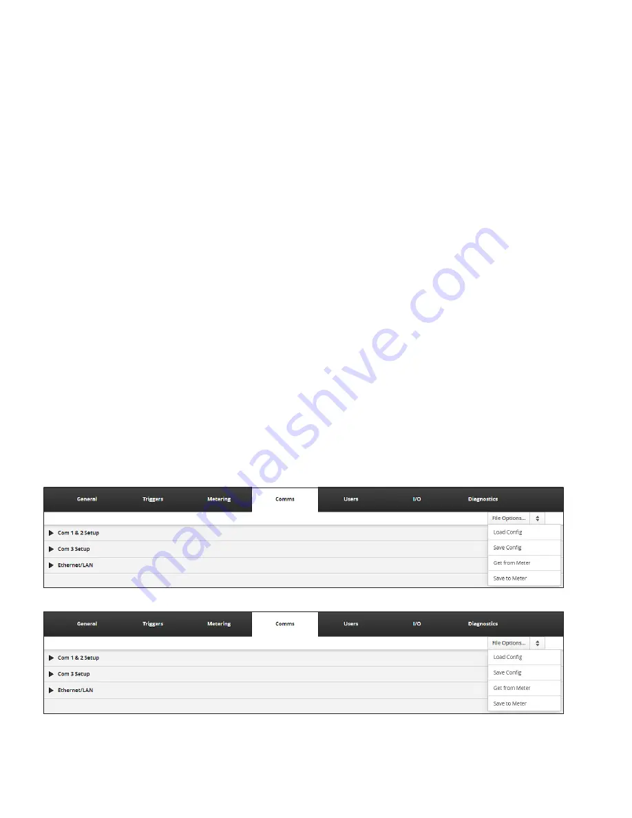
The User has options to Load & Save DNP3 database con-
figuration from the meter or a file. Each of these options
can accessed using the File Options dropdown at the top of
the Settings page.
otee:
N
Unless the User authenticates him/herself by valid
User name and password, these buttons will not be
operational. The User needs to press the Edit button
and enter credentials to access these options.
1. Load Config
The User can load a pre-configured DNP database
configuration from a file into the User interface to save
efforts. This file must be generated using the web
interface and must be present on the computer where
the web interface is being used.
Upon selecting this option, the User will be prompted
to select a configuration file. The User needs to select
an appropriate configuration file for loading into web
interface.
All configuration data will be available in the file will be load-
ed into the web interface and displayed for the User for fur-
ther operations. File data shall be loaded automatically into
the individual sections for each category. For example, if a
file has analog data (Object 30, 32), then it will be loaded
into the Analog Input section and if the file has binary coun-
ter data ( Object 20, 21, 22, 23) then it will be loaded into
the Counter input section of the web interface.
2. Save Config
When the User completes configuration of the DNP3
database, the User may wish to save the configuration
into a file on computer for future use and reference. By
using “Save Config” option on the web interface, the
User can save it on computer. The User will be prompt-
ed to select a location and provide a file name for the
configuration file.
Figure 14. Load & Save Buttons on the DNP Input/Output Page.
Figure 15. Configuration File Selected to Load.


