


68
Eaton Power Xpert 9395 UPS Installation and Operation Manual 164201716—Rev 13
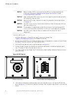
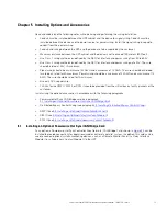
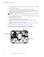
15. If required, install wiring from the REPO switch to the trip circuitry of the upstream protective devices. A
second contact block is provided on the REPO switch for this function (see
). The REPO switch
wiring must be in accordance with NEC Article 725 Class 2 requirements.
16. Reinstall the small top internal safety shield panel and secure with the cabinet mounted screws.
17. Reinstall the front door removed in Step 4 and secure with the retained hardware.
18. Close the door and secure the latch.
19. If removed, reinstall the safety shield panel removed in Step 7. Secure with the retained hardware.
20. If removed, reinstall the left front panel removed in Step 5 and secure with the retained hardware.
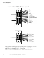
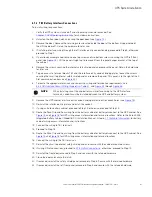
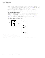
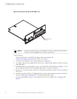
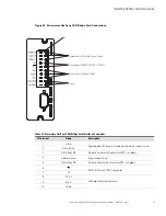
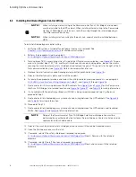
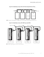
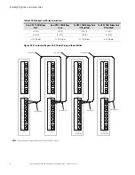
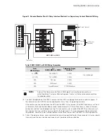
shows the wiring connections if the normally-closed REPO contacts are used, and
shows
alternative methods of connecting a REPO switch if using another manufacturer's switch.
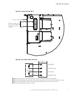
Figure 32. Normally Closed REPO Switch Wiring
3 (NO)
UPS TB1
REPO
Switch
(NC)
Twisted
Wires
1 (NC)
2 (Return)
4 (Return)
NOTE
REPO switch rating is 24 Vdc, 1A minimum.
NOTE
T
he REPO switch must be a latching-type switch not tied to any other circuits.
NOTE
REPO normally-open and normally-closed return terminals are separated on the terminal board but are electrically in common.
1
2


