


5
Instructional Booklet
IB02102006E
Effective May 2011
Type MVS (previously WLI)
metal-enclosed switchgear—
4.76 kV, 15.0 kV, 27.0 kV, and 38.0 kV
eaton corporation
www.eaton.com
installation
Refer to the shipping list for the location of bus, hardware, and all
other joining and installation material .
Joining type MVS enclosures
Access to MVS switch vertical sections containing switches
Each MVS switch is shipped from the factory in the “Closed” posi-
tion to maintain alignment during shipping and handling . The safety
interlocking prevents opening of the door of the vertical section
when the switch is closed . In order to gain access to the interior,
be sure that the switchgear is on a true and level surface . To open
a manually operated MVS switch, insert the operating handle and
push down . When the switch opens, the door may be opened . If the
switch is equipped with an electromechanical stored energy release
feature, follow the instructions on the instruction label located inside
the mechanism access door . If the switch is motor operated, it will
function identically to a manually operated switch .
When handling MVS switchgear, be sure that the switches are in
the “Closed” position . Do not operate MVS switches unless they
are setting on true and level surfaces . The definition of level is the
foundation cannot deviate more than ± 0 .0125 inches in 36 .00 inches
(0 .318 mm in 914 .4 mm) front to rear, left to right, and diagonally
at any point beneath the switchgear .
Identification of shipping splits
Refer to the front view drawing . Below this drawing, shipping splits
will be identified in relation to group numbers for each vertical
section . Normally, shipping sections will not exceed 154 .00 inches
(3911 .6 mm) in width .
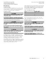
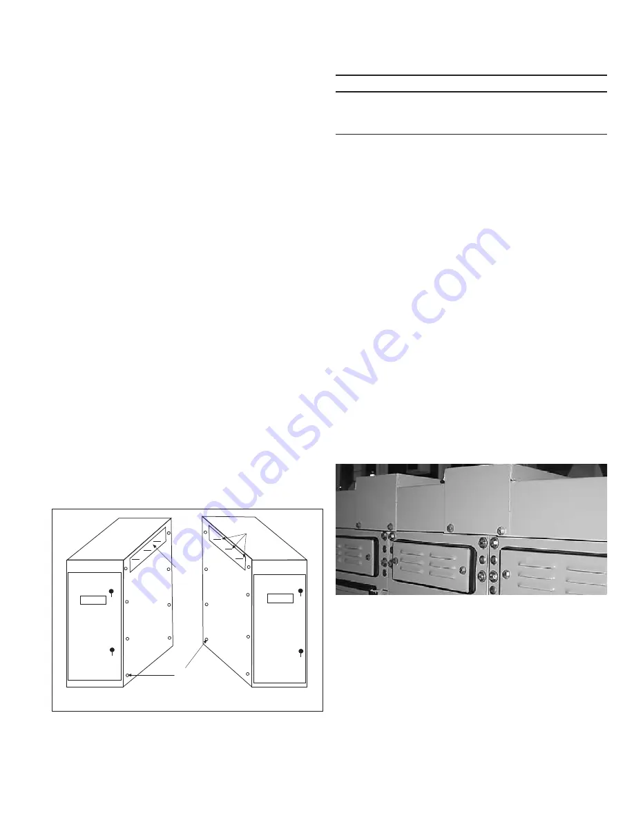
Procedures for joining MVS enclosures at shipping splits
Refer to
Figure 3
while completing the following procedure .
Step 1e:
Remove the eight 0 .375–16 inch bolts from each side sheet .
Step 2e:
Position the shipping sections next to each other . The eight
holes will usually match the holes in the adjacent side sheets but, in
some cases, it may be necessary to use an aligning tool such as a
punch to force the structures into alignment .
Step 3e:
Bolt the side sheets together using the eight bolts removed
from one side sheet in
Step 1
.
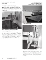
Figure 3. Joining MVS Enclosures
Step 4e:
Make the main and ground bus connections using splice
plates and the hardware furnished . The busbar is tin- or silver-plated .
To ensure a proper electrical connection, care should be taken to
protect the plating from damage .
DO NOT
use joint compound .
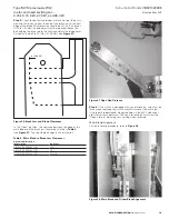
Cutout
Mounting
Bolts
Vertical Section to Left
Vertical Section to Right
L of
Busbar
C
CAUTION
CLEANING BUS JOINTS WITH ABRASIVE OR CHEMICAL CLEANSERS MAy
REMOVE PLATING. THIS COULD RESULT IN JOINT OVERHEATING.
WIPE THE BUS JOINTS WITH A CLEAN, DRy CLOTH TO CLEAN SURFACES.
Step 5e:
Bolted connections should be tightened to the torque values
given on
page 28
.
Installation of roof caps on outdoor units
Roof caps are necessary to complete the roof on all outdoor MVS
switchgear assemblies . Those not factory installed are shipped in
cartons that may be put within one or more of the vertical sections
if there is space, or they will be shipped separately .
Roofs requiring sealing compound
The following procedure details the work to be done to install each
cap on a caulking compound sealed roof joint .
Step 1e:
Remove the bolts securing the lifting lugs to the MVS
assembly . Remove the lifting lugs then replace the bolts just removed .
Step 2e:
Place a roof cap in position and start enough screws
(provided loose in a hardware package) to temporarily hold it in place
Step 3e:
Draw a pencil line down the side(s) on to the roof to mark
the edge(s) of the cap on the roof .
Step 4e:
Remove roof cap and apply a 0 .25 inch (6 .35 mm) bead of
caulking (provided by Eaton with the switch) along the inside edge
of the pencil line(s) .
Step 5e:
Hold the edge of the roof cap adjacent to the pencil line,
then rotate it over onto the bead(s) of caulk, aligning it with the bolt
holes in the roof as the action is completed .
Step 6e:
Install the supplied bolts and gasketed washers (rubber side
toward roof cap) in every bolt hole of roof cap . Tighten the bolts to
5 ft-lbs (6 .78 Nm) .
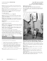
Figure 4. Roof Cap Installation
Step 7e:
Following instructions on the caulking container, smooth out
any excess caulk along the edges of the roof cap .
Step 8e:
Repeat this procedure until all roof caps have been installed .
For roofs that have edges turned up and formed caps to cover the
edges, it is only necessary to place the appropriate caps over the
roof edges and fasten them in place with the appropriate fasteners .
.


