


21
Instructional Booklet
IB02102006E
Effective May 2011
Type MVS (previously WLI)
metal-enclosed switchgear—
4.76 kV, 15.0 kV, 27.0 kV, and 38.0 kV
eaton corporation
www.eaton.com
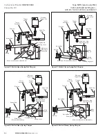
Method B
For the following procedure, refer to
Figure 29
.
Step 1e:
Remove components fastened to the hinge end terminal pad
and retain for later re-installation .
Step 2e:
Remove the four bolts holding the stationary hinge parts
and the terminal pad to the insulator . Retain the terminal pad for
later re-installation with the new blade and hinge assembly .
Step 3e:
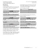
Remove the two bolts holding the break jaw to the upper
terminal . The jaw is now free .
Step 4e:
Replace the jaw, but only finger tighten its two mounting
bolts at this time .
Step 5e:
Install the new main blade assembly and terminal pad to the
insulator by installing the four bolts, but only finger tightening them
at this time .
Completing method A or B
Step 6e:
Align each blade following the instructions given
in “Closed-Open-Stop adjustment” section on
page 18
.
Step 7e:
Tighten the jaw mounting bolts .
Step 8e:
Method B only—tighten the blade and hinge assembly
mounting bolts .
Step 9e:
Method B only—install all previously retained components
fastened to the terminal pad .
Step 10e:
Align the flicker blade and arc chute following the
instructions given in “Closed-Open-Stop adjustment” section on
page 18
.
Step 11e:
Check the flicker blade functioning following the
instructions given in “Main blade alignment” section on
page 19
.
If the functioning is satisfactory, connect the drive rod to main blade .
Step 12e:
Check the switch for adjustments following the
instructions given in sections “Override of the switch interlock
safety latch” through “Arc chute alignment .”
Step 13e:
Perform the pre-operation check detailed on this page .
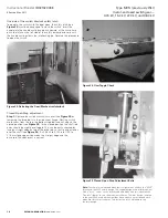
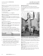
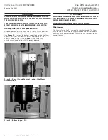
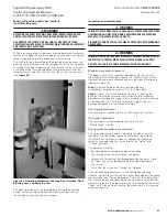
Spring replacement
The main spring is a large compression spring along the inside of
the switch frame on the operating handle side (see
Figure 30
) . For
several higher fault-close ratings, there is also an auxiliary spring
connected to the other end of the main shaft . If possible, close the
switch before removal of either spring .
Figure 30. Stored Energy Spring Replacement or Adjustment
Main spring replacement
Step 1e:
To disengage the main spring, remove the switch
mechanism cover (see
Figure 23
) .
Step 2e:
Take a 5/16”–18 threaded rod 4 .00 inches (101 .6 mm) long
and screw it into the rear end of the spring rod .
Step 3e:
Make a spacer 3 .00 inches (76 .2 mm) long from a pipe or
tube with a 1 .00 inch (25 .4 mm) I .D . Put this over the 5/16” rod and
the main spring rod .
Step 4e:
Take a washer with an outside diameter larger than the
spacer and place it on the rod .
Step 5e:
Turn a 5/16”–18 nut onto the rod until it is hand-tight and
then center the spacer .
Step 6e:
Use a tool to tighten the nut until the tension
on the pin at the front of the spring rod is released .
Step 7e:
Remove one or both of the retaining E-rings holding the pin
in place and remove the pin . The spring assembly is now free from
the shaft .
Step 8e:
Loosen the 5/16–18 nut on the piece of all-thread rod to
relieve the tension .
Step 9e:
Remove the piece of all thread from the spring rod . The rod
and spring now may be removed .
To install the main spring assembly, reverse this procedure .
Auxiliary spring replacement
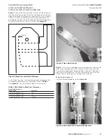
Step 1e:
To remove the auxiliary spring, put the switch in the
“Closed” position . While the compression spring is in its longest
condition, remove the elastic stop nut and bolt holding the spring
retaining rod to the small arm of the main shaft .
Step 2e:
Pull the spring rod away from its rear support . The spring is
now free of the rod .
To install the auxiliary spring, reverse the order of this procedure .
Shaft or bearing replacement
Step 1e:
Disengage the springs as instructed in “Closed-Open-Stop
adjustment” section on
page 18
.
Step 2e:
Remove the drive rods from the switch main shaft ears by
unbolting the connections .
Step 3e:
Remove the four bolts that hold the bearing support plates
on the end of the shaft opposite the operating mechanism .
Step 4e:
Slide the bearing support plates rearward, away from
the shaft .
Step 5e:
“Spring” the front of the unit slightly if the spring won’t
dislodge . The bearings can now be removed and replaced .
Step 6e:
To install the bearings or shaft, reverse the order of
this procedure .
Pre-operation check
After completing any maintenance, the alignment should be checked
(see
page 17
) . After completing any alignment, the switch should
be put through at least three “Close-Open” operations to check for
proper performance .