INM 937x-FB2-Px-SS Rev 1
9
IMPORTANT NOTE
937x-FB2 enclosures are factory-supplied with Option 1 grounding. If power is
applied locally, for example during commissioning, when the trunk cable shield is
NOT providing a ground connection, the spur cable shields must (temporarily) be
grounded according to Option 2.
When the trunk cable shield ground has been fully instated (or restored), the
grounding method should be returned to Option 1.
4 .2 .2 .2
Trunk shield grounded at host, spur cable shields grounded at barrier
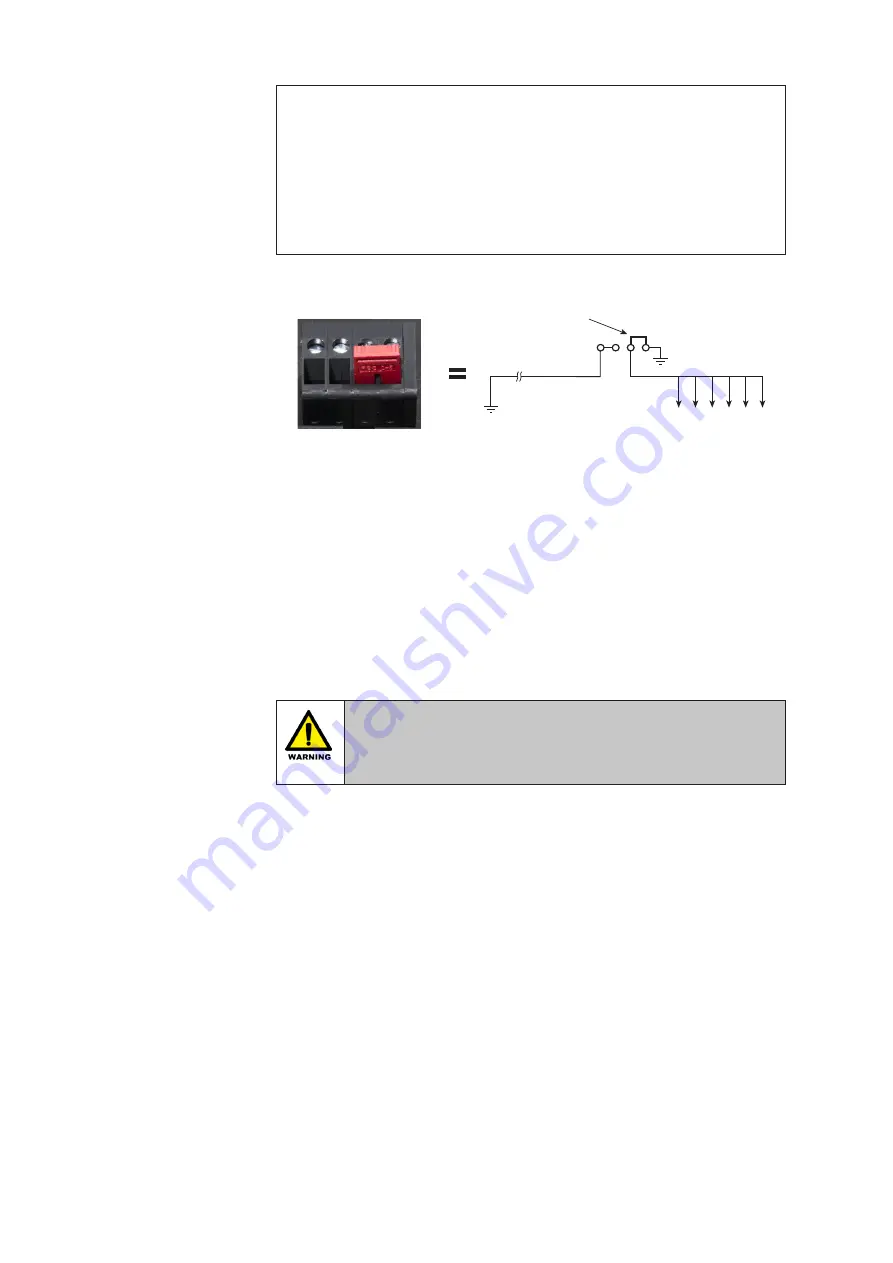
Figure 4 .2
- Option 2
With this arrangement, the fieldbus trunk shield is separated from the spur cable
shields. It should be adopted if plant or local regulations require that the spur cable
shields be grounded at the Fieldbus Barrier. For this arrangement, insert the link as
shown in Figure 4.2.
Note:
After configuring the required grounding option, tighten the screw terminals to
a recommended torque of 0.6 Nm.
4 .3 Trunk connections
Each enclosure is provided with two access holes for trunk cable glands; one for
the incoming trunk and another for onward linking to an additional enclosure, if
necessary.
WARNING !
No part of the Trunk Terminal Assembly may be worked while the
enclosure is powered, unless the environment is known to be
non-hazardous.
4 .3 .1 Trunk Terminal Area (TTA)
Inside the enclosure the trunk cables are terminated in a Trunk Terminal Area (TTA).
This is protected by a transparent cover with a warning label – both of these are
there to deter a user from working on the trunk connections without isolating trunk
power. See Figure 4.3.
Host
ground
Ground
stud
LINK
trunk shield
LK3
spur shields


