4
NPServe Users Guide
Users GUide
MN024002EN February 2017
Operation
1. By default, leave all checkboxes checked. Only during
certain custom procedures should the user pick and
choose which files to export.
2. Press “Create Configuration Archive” to begin
the export process. The web page will create a
downloadable link.
3. Click the downloadable link to save the file.
Save configuration
This is a minimal file upload to import a configuration
exported by NPServe.
Figure 8 . Save configuration
Devices and IO
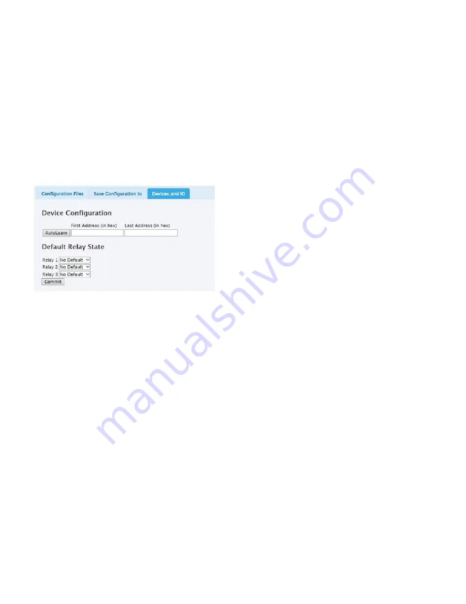
NPServe can autolearn INCOM devices connected to it.
The user can supply an address range to minimize autolearn
time, if the addresses are known a priori:
●
●
First Address – Autolearn scan starts at this address
and should be less than or equal to lowest address on
network.
●
●
Last Address – Autolearn scans up to and including this
address and should be greater than or equal to highest
address on network.
Possible Troubleshooting
1. If no INCOM devices are found, please make sure they
are properly connected.
2. Please refer to TD 17513 for wiring specifications.
Default relay state
1. On startup, the NPServe can by default energize or
leave idle the three output relays.
2. The default state for each relay is toggled by the pull
down box:
a. “No Default” – Relay is not energized on startup.
b. “Force Closed” – Relay is energized on startup and
cannot be changed by control.
3. Press the “Commit” button to save the relay states to
NPServe.
DNP SCADA
Status
●
●
Link Type – How NPServe hooks up to DNP Master; may
be UDP or RS-485
●
●
Link Status – Whether NPServe is responding to DNP
requests
●
●
Bytes Transmitted – How many bytes NPServe has
sent to Master since bootup or communications
reconfiguration
●
●
Bytes Received – How many bytes NPServe has received
since bootup or communications reconfiguration
otee:
N
This is a raw count of bytes, not what NPServe has
determined to be valid DNP.
●
●
Start Traffic Capture – Brings up a window showing the
raw communications on the DNP port (UDP or RS-485)
●
●
Stop Traffic Capture – Stops the traffic capture process
Communications
1. Select the Communications tab on the SCADA (DNP
Slave) web page to configure the communications
Network interface. Network options include RS485
serial or DNP over Ethernet (TCP or UDP).
2. Port 20000 is the default port for DNP3 communication
over Ethernet.
3. NPSERVE supports a single SCADA master. Up to
four (4) backup master IPs are supported, but only one
master may be active at a time.
4. To change the network interface, click the radio
button for the chosen interface, enter the requested
parameters, and click the <Submit Changes> button.
5. A built-in DNP sniffer provides traffic capture of the
DNP interaction between NPSERVE and the DNP
master. Click the <Start Traffic Capture> button to begin
the capture and the <Stop Traffic Capture> button to
stop. A new browser window will open and display the
bytes transmitted and received from NPSERVE.


