Installing Battery Cabinets
3-5
EATON
Powerware
®
9390 Integrated Battery Cabinet (Models IBC-S and IBC-L) Installation Manual
S
164201536 Rev D
www.eaton.com/powerquality
1.
Verify that the UPS is properly installed and secured. Refer to the appropriate
Powerware 9390 UPS Installation and Operation Manual, as referenced in
paragraph 1.6, for installation instructions.
2.
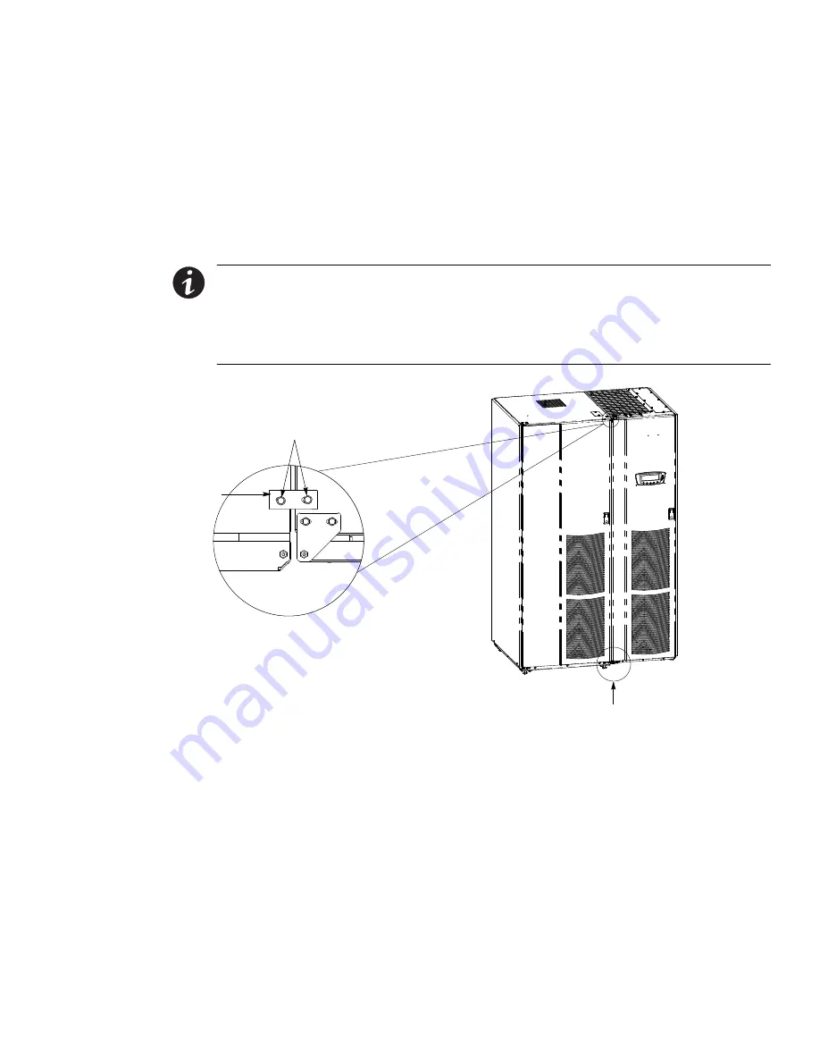
Roll the battery cabinet to an area near the left‐hand side of the UPS, as shown in
Figure 3‐3.
3.
Remove the field kit. The field kit is attached with cable ties to the frame inside
the door. Retain the field kit for later use.
NOTE
When a line-up-and-match UPS system is ordered together with battery cabinets,
the first battery cabinet is supplied with two cosmetic covers. The UPS cabinet,
additional battery cabinets, and other ancillary cabinets are supplied without cosmetic
covers.
NOTE
When cabinets are properly aligned, all cabinet doors are flush.
Screws from Kit
Bracket
from Kit
Battery Cabinet
UPS Cabinet
Large Bracket
Top View with Small Bracket
Figure 3‐3. UPS to IBC-S Joining Brackets
4.
If necessary, remove the cosmetic cover and hanger brackets from the left‐hand
side of the UPS. Save cover, screws, and brackets for later use.
5.
If necessary, remove the cosmetic cover and hanger brackets from the right‐hand
side of the battery cabinet. Save cover, screws, and brackets for later use.
6.
Remove the knockout plug on the bottom left side of the UPS cabinet inside
panel. Refer to Appendix A of the appropriate Powerware 9390 UPS Installation
and Operation Manual, as referenced in paragraph 1.6, for the location of the
knockout plug.


