Before You Begin
i-on40
Page 4
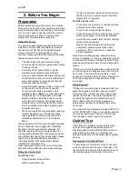
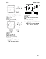
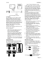
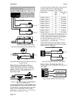
Figure 1 Opening the Control Unit.
WARNING:
When connected to the mains with
power applied mains voltages are present on the
shrouded heads of the terminal screws of the
mains connector (“8” in Figure 2).
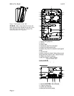
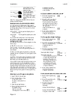
1. Central fixing keyhole.
2. Aerials.
3. Fixing holes.
4. Connector pins for Lid Tamper.
5. Printed circuit board (PCB).
6. Cable entry holes for detector and keypad
wiring.
7. Transformer.
8. Mains connector block. Note yellow power
rating label fitted next to the connector block.
9. Cable entry hole for mains.
10. Back Tamper switch (if fitted).
Figure 2 Control Unit
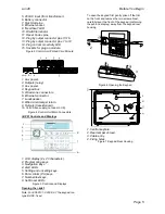
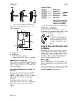
Control Unit PCB
1. Aerials (
CAUTION:
do not bend
).
2. Tamper connector.
3. USB socket (Mini B).
4. Ethernet link activity LEDs.
1
2
3
1
3
5
4
6
7
8
3
10
3
9
2
2
1
2
6
4
3
5
7
8
9
10
13
11
12
15
14


