


Installation
i-on30EXL/EXDL
Page 30
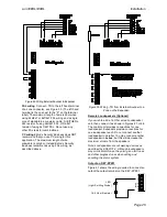
type on the expanders then use
Installer Menu
–
Detectors/Devices
– Wired Expander
after the
initial power up to change the wiring type for each
expander.
If the control unit lid is open then the display
shows:
Note that the alert LEDs round the navigation
key glow red. This is because the control unit
lid is off and the tamper is active.
9. Press
.
The display shows:
10. Press
.
The display shows:
11. Press
.
The display shows:
12. Press
.
The display shows:
At this point you must make the control unit
allocate an address to each of the connected
bus devices, as follows:
13. Go to each bus device. You can visit the
devices in any order, but if you visit them in
the order you want their address numbers to
appear then it will make subsequent
programming easier. The control unit assigns
the next free bus address to a bus device
when you make the device request a bus
address.
For keypads:
Hold down keys A and
until the display
shows a bus and device number. For example
the second keypad would be:
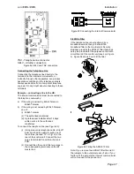
For expanders:
Open the lid (to make sure that the tamper
switch is open) and hold down the addressing
button (item 3 on Figures 15 and 17 ). When
you do so the control unit assigns the next
free address to that expander. The expander
gives a double “beep” confirmation tone and
shows its assigned address on the two-digit
LED display. Replace the lid.
NOTE: DO NOT request a bus address from two
different devices at the same time.
14. When you have visited all the connected bus
devices, go back to the keypad and press
.
The display shows:
15. Replace the control unit lid, making sure that
the lid tamper closes.
16. At this point you should leave the Installer
Menu to save the changes you have made,
see overleaf.
Note: To set the time and date use Installer Menu
- System Options
– Set Date & Time. See i-on
Range Engineering Guide for more information.
Diagnostic LED on Expanders
You may notice the DIAGNOSTIC LED flashing
on an expander PCB. The LED gives one, two,
three or four flashes a second. Each of these
sequences has the following meaning.
No. Flashes
Meaning
One
Communication with control unit
over bus is OK
Two
No communication over the bus
in the last 10 seconds.
Three
No bus address allocated to
expander
Four
No poll request received from
control unit in the last minute.
Transferring to Another Keypad
While in the Installer Menu, you can transfer to
any other wired keypad without leaving the
Installer Menu. To do this simply go to any other
keypad and enter the Installer access code. The
new keypad will pick up your position in the
Installer Menu. The keypad you have left will
briefly display the message “Installer session
transferred” for 5 seconds before reverting to the
time and date.
Leaving the Installer Menu
If you wish to leave the Installer Menu at any time.
1. Press
until the display shows the words:.
2. Press
to leave Installer menu.
(Press
if you do not want to leave the
menu.)
The display shows:
After a delay of anywhere between a few
seconds to a few 10s of seconds (depending
on the number of expanders fitted) the display
shows the time and date:
The system is ready for further programming.


