


i-on30EXL/EXDL
Installation
Page 17
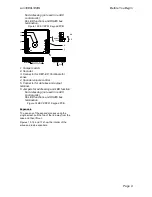
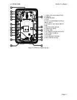
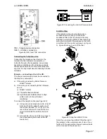
Connect the lead from the switch to the back
tamper connector on the PCB (see 4 in Figure 3).
Note that to be approved at Security Grade 3 you
must fit the lid/back tamper.
Step 2. Run Bus Cable
Please read “Cabling Requirements on page 12.
Step 3. Fit and Connect the
Keypad(s)
Siting the Keypad(s)
Do site the keypad(s):
Within the area protected by the alarm
system.
At a convenient height and location for the
user.
Out of sight of potential intruders.
Do NOT site the keypad(s):
Next to electronic equipment, particularly
computers, photocopiers or other radio
equipment, CAT 5 data lines or industrial
mains equipment.
Where the cable run from the control unit will
be longer than 100m (see Cable
Configuration and Length).
Note: Do not fit any keypad with an internal prox
reader closer than one meter to any other type of
prox reader. This includes other keypads with
prox readers, external prox readers such as the
KEY-EP, or prox readers used by other systems
(for example access control systems). If you
mount prox readers closer together than one
meter (including on the other side of walls) then
the two prox readers will interfere and may not
work correctly.
Fitting Keypads
Select which cable entry you are going to use and
break out the appropriate plastic sections.
Use 4mm x 25mm countersunk screws with a
thread suitable for the wall material in at least
three fixing holes when mounting the back of the
keypad on the wall.
i-KP01
For i-KP01 keypads on Grade 3 systems drill out
the hole for the back tamper using a 7mm bit (see
Figure 26).
Figure 26 Screw i-KP01 Back Box to Wall
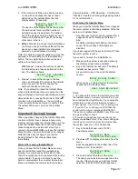
KEY-K01/KP01/KPZ01
Make sure the backplate is level and mark, drill
and plug at least three fixing holes. Screw the
backplate to the wall through the fixing holes
using the M4 screws.
Figure 27 Screw KEY-K01/KP01/KPZ01 Back Box
to Wall
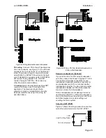
Connection
Figure 28 shows the wiring connections at the
keypad and control unit.
Figure 28 Connecting a Keypad to the Bus
Keypad Addressing
The control unit assigns addresses to all devices
connected to the bus cable. You must start this


