background image

54

Eaton Green Motion DC EV Charger User’s Manual P-164001189—Rev 01

C

Chhaapptteerr 99 P

Prroodduucctt S

Sppeecciiffiiccaattiioonnss

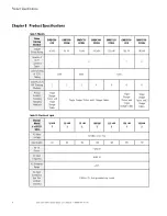
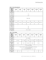
Table 9. Models

Eaton

Catalog

Number

GMDC50-

CCS

GMDC50-

CCSX2

GMDC75-

CCSX2

GMDC100-

CCSX2

GMDC125-

CCSX2

GMDC150-

CCS

GMDC150-

CCSX2

Charger

Power Rating

50 kW

50 kW

75 kW

100 kW

125 kW

150 kW

150 kW

Quantity of

CCS1

Connector

Cables

1

2

1

2

Current Rating

of CCS1

Cabling

125A

200A

300A

Quantity of 25

kW Charging

Modules

2

2

3

4

5

6

6

Product

Contents

(Excluding
Packaging
Materials)

Single

Charger

Station and

Single

Charger

Cable

Single Charger Station and 2 Charger Cables

Single

Charger

Station and

Single

Charger Cable

Single

Charger

Station and 2

Charger

Cables

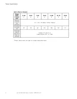
Table 10. Electrical Input

Charger

Model

# of CCS1

cables

50 kW

1

50 kW

2

75 kW

2

100 kW

2

125 kW

2

150 kW

1

150 kW

2

AC Input

Voltage

3Ø 480 +10%/-15%

Input Amp(s)

64

64

96

128

160

192

192

No. Of

Phases

3 phases

AC Input

Frequency

50/60 Hz

AC Frequency

Range

±10%

AC Input

Connection

Type (line
cord/hard

wire/etc)

3-Wire + PE, from grounded wye source

Product Specifications

Summary of Contents for Green Motion GMDC50-CCS

Page 1: ...p n P 164001189 Revision 01 50 150 kW DC Electric Vehicle Charger User s Manual Eaton Green Motion DC EV Charger...

Page 2: ...at your facility Our suite of backup power power distribution and power management products are designed to protect you from a host of threats including power outages surges and lighting strikes and...

Page 3: ...2 3 2 3 Construct the Foundation 13 3 3 Standard Wiring Preparation 17 3 4 Inspect and Unpack the DC Charger 20 3 4 1 Packaging 20 3 4 2 Transporting 21 3 4 3 Inspecting and Unpacking 21 4 4 I In ns s...

Page 4: ...nual P 164001189 Rev 01 8 8 T Tr ro ou ub blle es sh ho oo ot tiin ng g 5 52 2 8 1 Typical Alarms and Conditions 52 9 9 P Pr ro od du uc ct t S Sp pe ec ciif fiic ca at tiio on ns s 5 54 4 1 10 0 W Wa...

Page 5: ...n Base Dimensions 13 Figure 7 Concrete Foundation Cross Section 14 Figure 8 Protective Bollard Guard Post Location 15 Figure 9 Protective Bollard Guard Post Front View 16 Figure 10 DC Charger Wiring D...

Page 6: ...al Hardware Specification 18 Table 5 Crate Packaging Dimensions 20 Table 6 LED Status Indicator States 40 Table 7 DC EV Charger Power Sharing Scenarios 42 Table 8 DC Charger Maintenance Cycle 50 Table...

Page 7: ...fleet charging Other applications include any EV charging needs that do not require a credit card reader for payment processing E Ea at to on n C Ch ha ar rg giin ng g N Ne et tw wo or rk k M Ma an na...

Page 8: ...2 Eaton Green Motion DC EV Charger User s Manual P 164001189 Rev 01 Figure 1 Eaton Green Motion DC EV Charger Introduction...

Page 9: ...350 4 150 180 132 Ford e Transit van 110 1 6 67 13 4 53 6 115 30 66 F 150 EV 230 2 3 98 19 6 78 4 41 138 Freightliner EM2 class 6 180 0 9 194 38 8 155 2 60 108 Freightliner EM2 class 7 250 1 0 262 52...

Page 10: ...reen Motion 50 150 kW DC EV Charger is a stand alone cabinet electric vehicle charging station Figure 2 DC EV Charger Component Locations Charging Connector Cable Door Lock Touch Screen Display LED St...

Page 11: ...cedure before beginning the work 1 1 5 5 C Co on nv ve en nt tiio on ns s U Us se ed d iin n T Th hiis s M Ma an nu ua all This manual uses these type conventions Bold type highlights important concep...

Page 12: ...estion this manual does not answer Please call the Customer Reliability Center at 24x7 EV Driver Support 1 800 796 0478 24x7 Technical Support 1 800 843 9433 Installation Support 1 800 843 9433 Please...

Page 13: ...he Eaton Green Motion DC EV Charger Doors are to be kept closed and opened by AUTHORIZED SERVICE PERSONNEL ONLY Please follow the below safety precautions to prevent bodily injuries and property damag...

Page 14: ...observed contact an authorized service provider immediately WARNING In case of heavy rain and thunder please use caution when operating the charger Consider delaying charging until the storm subsides...

Page 15: ...125 kW DC EV Chargers and 35 C to 50 C for the 150 kW DC EV Chargers CAUTION The charger should meet the protection level requirements in chapter 10 5 1 of GB T 18487 1 2015 and the environmental prot...

Page 16: ...stem 3 3 2 2 P Pr re ep pa ar riin ng g t th he e S Siit te e For the Eaton Green Motion DC EV Charger to operate at peak efficiency the installation site should meet the environmental parameters outl...

Page 17: ...terials or corrosive fumes 3 Wiring and conduit needed to connect the charger is appropriately sized and located properly to allow connection to the charger 4 The charging connectors can reach the cha...

Page 18: ...tails the recommended minimum distance to be maintained during the site installation Figure 5 Charger Installation Clearances DC Charger 36 914 mm 36 914 mm 19 7 500 mm 19 7 500 mm Rear Front Top View...

Page 19: ...depth When preparing the foundation and cabling pay attention to cable through hole and expansion bolt locations See Figure 6 for details Figure 6 Foundation Base Dimensions 21 65 550 16 78 426 12 8...

Page 20: ...power cables shall be in accordance with NEC guidelines and local electrical codes Cable design shall be selected according to the number of chargers and the type power voltage and current level of t...

Page 21: ...r The distance between two bollards on the same side of the charger is 34 inches 850mm as shown in Figure 8 Figure 8 Protective Bollard Guard Post Location DC Charger Front of the enclosure Rear of th...

Page 22: ...16 Eaton Green Motion DC EV Charger User s Manual P 164001189 Rev 01 Figure 9 Protective Bollard Guard Post Front View Bollards Safety Guard Posts Installation Plan and Unpacking...

Page 23: ...98 Efficiency 94 at nominal output power Input voltage A 480V Input voltage B 277V The Eaton Green Motion 50 150 kW DC EV Charger must be wired with a grounded WYE input as shown in Figure 10 N NO OT...

Page 24: ...ider the following guidelines and consult the table below Table 3 External Wiring and Upstream Protection Requirements Charger rating 50 kW 75 kW 100 kW 125 kW 150 kW Line cable size AWG or Kcmil 3 1...

Page 25: ...C 250 122 If the ambient temperature is greater than 30 C larger conductors are to be selected in accordance with the correction factors of the IEC Do not use wire larger than 350 kcmil S St ta an nd...

Page 26: ...a ag giin ng g The charger is delivered in a specialized wood packaging The following figure shows the packaging and size information for the charger Figure 12 DC EV Charger Transport Packaging Front...

Page 27: ...en 40 C and 70 C N NO OT TE E 2 2 It is recommended to transport the charger to its final destination before removing the original packaging 3 3 4 4 3 3 I In ns sp pe ec ct tiin ng g a an nd d U Un np...

Page 28: ...ox and foam packaging material Straighten all the tongue buckles on the steel belt box with a screwdriver Remove the top steel strip planks Remove the left and right steel strip planks Remove the fron...

Page 29: ...op four ring hole screws Step 3 Remove the fixing screws between the charger and the pallet N NO OT TE E There are two cases when removing the fixing screws between the charger and the pallet CASE 1 W...

Page 30: ...on Green Motion DC EV Charger User s Manual P 164001189 Rev 01 Step 3 continued CASE 2 When the hole in the screw position of the base of the charger is small and the socket cannot be inserted Install...

Page 31: ...Eaton Green Motion DC EV Charger User s Manual P 164001189 Rev 01 25 Step 4 Lift the charger to the cement platform Installation...

Page 32: ...26 Eaton Green Motion DC EV Charger User s Manual P 164001189 Rev 01 Step 5 Attach the charger to concrete pad Step 6 Connect the charger Installation...

Page 33: ...01189 Rev 01 27 Step 6 continued N NO OT TE E 1 1 After wiring is complete inspect all electrical connections prior to energizing the charger N NO OT TE E 2 2 When charger is powered on the LCD screen...

Page 34: ...rger system configuration activities when system is idle otherwise charging session will be interrupted and or cause charger session errors 5 5 1 1 S Se et tt tiin ng g A Ad dm miin niis st tr ra at t...

Page 35: ...wo or rk k C Co on nn ne ec ct tiio on n N NO OT TE E OCPP Open Charge Point Protocol maintains communication between the charger and system network Figure 14 Connect Network Cable RJ45 Port Location...

Page 36: ...Green Motion DC EV Charger User s Manual P 164001189 Rev 01 Step 1 Select Help Administration Enter Admin Password Network Settings Step 2 Connection Method Select Ethernet then open DCHP System Confi...

Page 37: ...pment Set the product Serial Number SN Step 5 Turn the DCHP on and the URL is filled in with the cloud platform address obtained by the customer N NO OT TE E The URL of the cloud platform and the char...

Page 38: ...er before leaving the factory N NO OT TE E The MAC address is globally unique and cannot be changed Step 7 After the customer cloud platform is created reboot the charger and wait 1 2 minutes If the s...

Page 39: ...189 Rev 01 33 5 5 3 3 C Ce ellllu ulla ar r N Ne et tw wo or rk k S Se et tt tiin ng gs s The following instructions are only used when replacing the factory installed Eaton ChargeLab CNM SIM card wit...

Page 40: ...34 Eaton Green Motion DC EV Charger User s Manual P 164001189 Rev 01 Step 2 Step 3 System Configuration...

Page 41: ...Green Motion DC EV Charger User s Manual P 164001189 Rev 01 35 Step 4 Step 5 After the charger is powered on set up 4G Select Help Administration Enter Admin Password Network Settings System Configur...

Page 42: ...arger User s Manual P 164001189 Rev 01 Step 6 Select Connection Method Select 4G Step 7 Select CPO Settings then open CPO Mode enter the OCPP URL Step 8 Select About Equipment set the product SN seria...

Page 43: ...operator of the 4G card and ask them to provide the local APN and then enter the current location Step 10 Wait 1 minute If the signal icon is white as shown in the second image below the 4G module has...

Page 44: ...1189 Rev 01 5 5 4 4 C CP PO O s se et tt tiin ng gs s N NO OT TE E CPO Charge Point Operators is software that manages the charging transactions performed at the DC Charger Select Help Administration...

Page 45: ...otion DC EV Charger User s Manual P 164001189 Rev 01 39 5 5 5 5 Q Qu ue er ry yiin ng g t th he e S So of ft tw wa ar re e V Ve er rs siio on n N Nu um mb be er rs s Select Help Administration System...

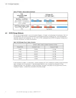
Page 46: ...s s I In nd diic ca at to or rs s Figure 15 LED Status Indicators and Location Center Left Right Table 6 LED Status Indicator States State Left Connector Right Connector DC Charger LED Left Center Rig...

Page 47: ...shes charging but the cable is still connected and user B is charging Blue Blue Green Ready Charging Blue Blue Green Ready Charged Blue Blue Green Loss of Power Loss of Power Charger is out of order d...

Page 48: ...ession With two dispenser connectors present each connector can carry 100 of the rated power up to 300A but power sharing occurs when both connectors are used simultaneously Table 7 DC EV Charger Powe...

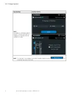
Page 49: ...ce e 6 6 3 3 1 1 U Us se er r O Op pe er ra at tiio on n S St te ep ps s Operating Steps Operating Interface Step 1 Tap the screen Select the connector See step 2 1 If card is tapped first you should...

Page 50: ...ps Operating Interface Step 2 2 If a charging connector has been connected to the vehicle wait for the connection to register The session can then be authorized by tapping your card or scanning the QR...

Page 51: ...01189 Rev 01 45 Operating Steps Operating Interface Step 3 Once the authorization is complete the charging session will begin Step 4 While the vehicle is charging charging data can be viewed on the LC...

Page 52: ...5 The charging time and charging capacity is displayed on the final screen When the charging session has ended return the connector to it s holder NOTE If it is necessary to stop a charging session b...

Page 53: ...ange charge type 9 Help 5 Charging capacity 10 Charging voltage 6 6 4 4 P Pr re ec ca au ut tiio on ns s If the screen shows a machine failure do not operate please contact Eaton or authorized service...

Page 54: ...gency Stop button to safely secure power to the charger Once the EPO button has been pressed the charging session will be stopped and a warning will be shown on the display See Figure 17 for Emergency...

Page 55: ...al components for signs of damage Verify that the input power cables are securely connected to the input terminals Check for and remove any dust accumulated in the cabinet once a month to allow for pr...

Page 56: ...front and back door vents with dust proof cotton Check the internal wiring regularly Check for loose connections Check connection terminals and insulation for discoloration or peeling replace damaged...

Page 57: ...em me en nt t 1 Open the front door 2 Loosen the two M6 bolts three M4 nuts and two fixing plates 3 Remove the filter 1 Install the new filter and two fixing plates 2 Tighten the two M6 bolts and thre...

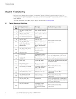
Page 58: ...hSetValue The insulation test voltage does not meet the preset value 13 CM_GPRS_COMM_ERROR Internal network communication error 14 ARRESTER_FAULT SPD fault 15 STOP_SW_ACT The emergency power off EPO b...

Page 59: ...is water in the cabinet 44 CM_INS_COMM_ERR Insulation tester communication error Try rebooting the charger If there is no improvement please contact an Eaton service representative 45 CM_ACinput_COMM_...

Page 60: ...Quantity of 25 kW Charging Modules 2 2 3 4 5 6 6 Product Contents Excluding Packaging Materials Single Charger Station and Single Charger Cable Single Charger Station and 2 Charger Cables Single Charg...

Page 61: ...r Factor Full Load 0 98 Half Load 0 95 Input Voltage Swell 120 for 5 cycles Table 11 Electrical Output Charger Model of CCS1 cables 50 kW 1 50 kW 2 75 kW 2 100 kW 2 125 kW 2 150 kW 1 150 kW 2 DC Outpu...

Page 62: ...Alarm resets when connector detects 90 C Connector detects 105 C charging output disconnects and terminates current session of charging Surge Protection Joules Detail IEEE C62 41 Category B3 C1 Remot...

Page 63: ...ss Protection IP54 NEMA 3R Seismic Rating AC156 or equivalent Packaging Vibration Drop Shock ISTA 3B Other Certifications Eaton Cybersecurity Standard ISO IEC 15118 Plug and Charge portion only DIN 70...

Page 64: ...kW 2 125 kW 2 150 kW 1 150 kW 2 Dimensions D x W x H Feet millimeters 30 7 32 8 71 8 780mm 834mm 1823mm Unit Weight lbs 783 796 827 855 888 924 937 Output Cable Length ft measured at exiting from enc...

Page 65: ...reen Motion 50 150 kW DC EV Charger warranty please click on the link or copy the address to download from the Eaton website Limited Factory Warranty for Eaton Green Motion 50 150kW DC EV Fast Charger...

Page 66: ...P 16400118901 P 164001189 01...

Reviews: