


3
FC6 / FC6-AU Fan controller user manual
FC6/FC6-AU FAN CONTROLLER
www.eaton.com
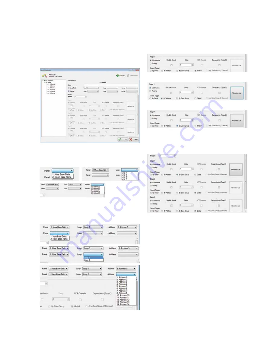
5. Select the output channel, one to six in the
configuration screen
Select the “Enabled” in the configuration screen
Select the “Loop Mode” in the configuration screen
Select the “Confirm” in the configuration screen
Figure 6.
In the Panel, Loop and Address icons (drop down boxes)
across from the Loop Mode, select where the control
device you are going to use (CFC301 ZMU, MCOM,
MCOM-S, MCOM-FC) is located on the system.
In the Panel, Loop and Address icons (drop down boxes)
across from the Confirm, select where the feedback
device you are going to use (CFC301 Technical Input,
MCIM) is located on the system. This only needs to be
set if there is feedback from the fan itself.
If you use 6 channels, you need to open the 6 channels
which will allow you to write 6 rules.
6. Select in the configuration screen which cause and
effect is needed for the output to activate.
Figure 7.
Global
By address
By zone group
Select up to 3 stages to have a combination of different
cause and effect results.
Figure 8.
PR209-166-504-08
January 2018


