background image

Preparation of cables to be spliced

Step 1

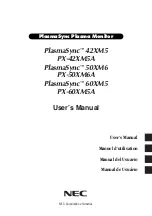
Overlap both cables.
Locate the splice centerline as shown in Figure 1.
On cable #2 measure out 24" (610 mm) from the splice 

centerline and cut off the cable. (This will ensure there is an 

adequate length of concentric neutral wire to reconnect the 

neutral after splice installation.)
Cut off cable #1 at the splice centerline with a smooth 

square cut.
Remove the outer jacket of cable #2 to 30" (762 mm) and 

remove the outer jacket of cable #1 to 12" (305 mm).
Fold back the concentric neutral wires.

Cut off cable #2 at the splice centerline with a smooth square 
cut.

Check the jacket strip back dimensions from the splice 
centerline to the outer jacket cutoff.

Step 2

Measure from the end of both cables and remove 3-5/8" (92 

mm) of the semi-con insulation shield. (See Figure 2).

Step 3

Measure back from the end of both cables and remove 

1-1/8" (29 mm) of the cable insulation, exposing the bare 

conductor. Remove sharp edge of insulation by beveling at 

45° angle for approximately 1/8" (3 mm). (See Figure 3).
Clean the cable insulation with an approved cleaner. Wipe 

the cleaner towards the insulation shield only. 

Figure 2.  Insulation shield stripback.

INSULATION

INSULATION SHIELD 

INSULATION SHIELD

12"

(305 mm)

6"

(153 mm)

5

/

8

"

(92 mm)

5

/

8

"

(92 mm)

CABLE #1

CABLE 

#2

Figure 3. Insulation stripback.

1/8"

(3 mm)

1 1/8"

(29  mm)

1/8"

(3 mm)

  11/8"

(29 mm)

CONDUCTOR

CONDUCTOR

CLEAN CABLE 

TOWARD INSULATION SHIELD

3 5/8"

(92 mm)

CABLE #1

CABLE #2

3 5/8"

(92 mm)

 CAUTION 

Be careful not to nick or damage the cable insulation 

during this step. 

 CAUTION 

Take care not to damage the conductor during this step. 

Figure 1.  Illustration of cables to be spliced.

CABLE 

JACKET

INSULATION

SHIELD

BEND NEUTRAL 

WIRES DOWN AND OUT 

OF THE WAY

BEND NEUTRAL 

WIRES DOWN

AND OUT OF 

THE WAY

SPLICE 

CENTERLINE

12"

(305 mm)

CABLE #1

CABLE 

#2

6"

(153 mm)

30"

(762 mm)

24"

(610 mm)

CABLE 

JACKET

2

15 KV AND 25 KV CLASS EZ II SPLICE INSTALLATION INSTRUCTIONS

   MN650007EN   January 2016   

Summary of Contents for EZ II Series

Page 1: ...15 kV and 25 kV class EZ II splice installation instructions For A B and C cable ranges only COOPER POWER SERIES Splices MN650007EN Effective January 2016 Supersedes April 2015...

Page 2: ...FOR A PARTICULAR PURPOSE OR MERCHANTABILITY OTHER THAN THOSE SPECIFICALLY SET OUT IN ANY EXISTING CONTRACT BETWEEN THE PARTIES ANY SUCH CONTRACT STATES THE ENTIRE OBLIGATION OF EATON THE CONTENTS OF T...

Page 3: ...Contents SAFETY INFORMATION Safety Information iv PRODUCT INFORMATION Introduction 1 Acceptance and Initial Inspection 1 Handling and Storage 1 Standards 1 Description 1 PREPARATION OF CABLES TO BE S...

Page 4: ...king around high voltage lines and equipment and support our Safety For Life mission Safety information DANGER Hazardous voltage Contact with hazardous voltage will cause death or severe personal inju...

Page 5: ...on receipt inspect the shipping container for signs of damage Unpack the splice and inspect it thoroughly for damage incurred during shipment If damage is discovered file a claim with the carrier imme...

Page 6: ...1 1 8 29 mm of the cable insulation exposing the bare conductor Remove sharp edge of insulation by beveling at 45 angle for approximately 1 8 3 mm See Figure 3 Clean the cable insulation with an appr...

Page 7: ...rds the end of the connector Rotate each crimp 90 Install as many crimps as possible without overlapping crimps Note N After crimping remove any sharp edges or raised points on the compression connect...

Page 8: ...rejacketing sleeve per the manufacturer s recommended instructions Figure 6 Cutaway of installed splice CONCENTRIC NEUTRAL CONNECTED TOGETHER SINGLE CONCENTRIC NEUTRAL BOTH ENDS CENTER SPLICE BETWEEN...

Page 9: ...This page is intentionally left blank 5 15 KV AND 25 KV CLASS EZ II SPLICE INSTALLATION INSTRUCTIONS MN650007EN January 2016...

Page 10: ...This page is intentionally left blank 6 15 KV AND 25 KV CLASS EZ II SPLICE INSTALLATION INSTRUCTIONS MN650007EN January 2016...

Page 11: ...This page is intentionally left blank 7 15 KV AND 25 KV CLASS EZ II SPLICE INSTALLATION INSTRUCTIONS MN650007EN January 2016...

Page 12: ...on 2300 Badger Drive Waukesha WI 53188 United States Eaton com cooperpowerseries 2016 Eaton All Rights Reserved Printed in USA Publication No MN650007EN Rev 01 Supersedes 5000050839 Rev 03 SAFETY FOR...

Reviews: