background image

4

External Battery Cabinets

Chapter 2       Safety Warnings

IMPORTANT SAFETY INSTRUCTIONS SAVE THESE INSTRUCTIONS

This manual contains important instructions that should be followed during installation and 
maintenance of the accessories and batteries. Read all instructions before operating the equipment 
and save this manual for future reference.

The Accessories are designed for industrial or computer room applications with UPS, and contains 
safety shields behind the door and front panels. However, any installation and operations should be 
handled with appropriate care.

DANGER

The Accessories may contain LETHAL VOLTAGES. All repairs and service should be performed by 
AUTHORISED SERVICE PERSONNEL ONLY. 

WARNING

• 

The Accessories are suitable for mounting on concrete or other non-combustible surfaces only.

• 

The terminals may carry live voltage even when the Accessory is connected to UPS.

• 

To reduce the risk of fire or electric shock, install the Accessory and UPS in a temperature and 
humidity controlled, indoor environment, free of conductive contaminants. Ambient temperature 
must not exceed 40°C (104°F). Do not operate near water or excessive humidity (95% 
maximum). 

• 

As a result of the connected loads high leakage current is possible. Connection to earth ground is 
required for safety and proper product operation. Do not check Accessory or UPS operation by 
any action that includes removal of the earth (ground) connection with loads attached.

• 

Ensure all power is disconnected before performing installation or service.

• 

Batteries can present a risk of electrical shock or burn as high short-circuits current. The following 
precautions should be observed: 1) Remove watches, rings, or other metal objects;2) Use tools 
with insulated handles; 3) Do not lay tools or metal parts on top of batteries; 4) Wear rubber 
gloves and boots.

• 

ELECTRIC ENERGY HAZARD. Do not attempt to alter any Accessory, UPS or battery wiring or 
connectors. Attempting to alter wiring can cause injury.

• 

Do not open or mutilate batteries. Released electrolyte is harmful to the skin and eyes. It may be 
toxic.

CAUTION

• 

Installation or service should be performed by qualified service personnel knowledgeable of 
UPS, UPS Accessory and battery systems, and required precautions. Keep unauthorized 
personnel away from equipment. Consider all warnings, cautions, and notes before installing or 
servicing equipment. DO NOT DISCONNECT the batteries while the UPS is in Battery mode.

• 

Batteries may only be replaced with the same number and type by authorized service 
personnel. No user serviceable parts.

• 

The UPS system has been evaluated for use with a maximum of two EBCs (Double EBC). Use 
of any other configuration may result in fire, death, and voiding of the warranty.

• 

Disconnect the charging source prior to connecting or disconnecting battery terminals.

• 

Determine if the battery is inadvertently grounded. If it is, remove the source of the ground.

• 

Contacting any part of a grounded battery can cause a risk of electric shock. An electric shock is 
less likely if you disconnect the grounding connection before you work on the batteries.

Summary of Contents for Double EBC

Page 1: ...External Battery Cabinets Installation and Operation Manual Eaton UPS Accessories...

Page 2: ......

Page 3: ...ment and save this manual for future reference 2014 Eaton Corporation All Rights Reserved The contents of this manual are the copyright of the publisher and may not be reproduced even extracts unless...

Page 4: ...Preliminary Installation Information 15 4 2 Unloading the EBC Cabinet from the Pallet 15 4 3 External Power Cables Connecting 17 4 4 Battery and cable Installation 19 4 5 External Signaling Cables Co...

Page 5: ...on Pallet wood container removed 14 Figure 3 6 Battery Breaker Location 14 Figure 4 1 Removing the Front Shipping Bracket 16 Figure 4 2 Attaching the Ramp to the Pallet 16 Figure 4 3 Removing the Rear...

Page 6: ...06 External Battery Cabinets List of Tables Table 3 1 EBC CabinetWeights 7 Table 3 2 EBC Cabinet Clearances 7 Table 3 3 External PowerWiring Requirements for 93E and 93PM 11 Table 3 4 BatteryType 12...

Page 7: ...uit breaker within each cabinet provides protection and servicing isolation Figure 1 1 shows the Eaton Single EBC and Eaton Double EBC Startup and operational checks must be performed by an authorized...

Page 8: ...available Use CSB HRL and C D MRX batteries for dimension reference Single EBC A single cabinet fitted with battery circuit breaker and 5 trays shall house 40 batteries of 200 320W Cell rating Double...

Page 9: ...waste centre This symbol indicates that you should not discard waste electrical or electronic equipment WEEE in the trash For proper disposal contact your local recycling reuse or hazardous waste cent...

Page 10: ...Ensure all power is disconnected before performing installation or service Batteries can present a risk of electrical shock or burn as high short circuits current The following precautions should be...

Page 11: ...ry warranty Refer toTerms and Conditions of Sale with Battery Replacement Coverage and the Battery Replacement Price Book for more information These documents can be found at www eaton com powerqualit...

Page 12: ...ational checks for parallel systems or installations with accessory cabinets must be performed by an authorized Eaton Customer Service Engineer or the warranty terms may become void This service is of...

Page 13: ...ents for operation of the UPS and Accessories are AmbientTemperature Range 0 40 C 32 104 F Recommended Operating Range 20 25 C 68 77 F Maximum Relative Humidity 95 noncondensing Table 3 1 EBC Cabinet...

Page 14: ...84 120 4 72 270 10 63 89 8 3 54 145 5 71 570 22 44 650 25 59 225 8 86 1169 7 46 05 92 3 62 702 27 64 182 5 7 19 FRONT VIEW RIGHT VIEW REAR VIEW Figure 3 1 Single EBC Dimensions Front and Right Side V...

Page 15: ...d Bottom Views Dimensions are in millimetres inches 1271 20 50 04 1877 7 73 93 145 5 71 225 8 86 570 22 44 650 25 59 92 3 62 702 27 64 148 3 5 84 182 5 7 19 818 5 10 32 22 270 10 63 270 10 63 1169 7 4...

Page 16: ...lation and Operation manual listed in corresponding paragraph for UPS cabinet conduit and terminal specifications and locations The term line up and match refers to accessory cabinets that are physica...

Page 17: ...354 M10 Hex Ground 95 1 1 M10 Bolt Monting 40 354 M10 Hex 120 150 1 2 3 4 Battery 185 1 1 M10 Bolt Monting 40 354 M10 Hex battery 185 1 1 M10 Bolt Monting 40 354 M10 Hex Ground 185 1 1 M10 Bolt Monti...

Page 18: ...12 370MRX UPS12 400 MRX UPS12 440MRX UPS12 475 MRX UPS12 490MRX UPS12 520 MRX UPS12 550MRX UPS12 600 MRX UPS12 630 MRX Battery Quantity Eaton Single EBC 40 per string 1 string per cabinet 40 per strin...

Page 19: ...tip over Take care of drop when lift the EBC from carton While waiting for installation protect the unpacked cabinet from moisture dust and other harmful contaminants Failure to store and protect the...

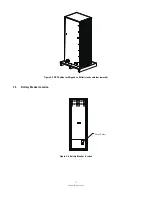
Page 20: ...14 External Battery Cabinets Figure 3 5 EBC Cabinet as Shipped on Pallet wood container removed 3 5 Battery Breaker Location Figure 3 6 Battery Breaker Location Battery Breaker...

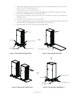
Page 21: ...he front of the pallet c Attach the ramp extension to the front of the ramp by inserting the tabs on the extension into the slots at the bottom of the ramp 4 If the leveling feet are not fully retract...

Page 22: ...l 10 If permanently mounting the system proceed to Step 11 11 Using the retained hardware reinstall the shipping brackets removed in Step 2 and Step 5 to the front and rear of the EBC with the angle f...

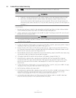
Page 23: ...Eaton UPS Installation and Operation manual or UPS cabinet terminal locations and termination requirements 5 Let the EBC stand side by side to the UPS and secure the DC battery cables to the EBC botto...

Page 24: ...ations Double EBC Double EBC Single EBC Ground tray connectors EBC1 EBC2 Top View Ground Cable EBC 1 Ground Cable Top View EBC 2 To Double EBC RS232 To Mini Slot communication Bay 2 DC Input from Exte...

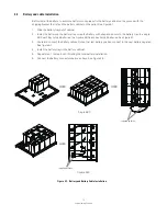
Page 25: ...trap and secure to the battery tray In a single EBC each tray holds 8 batteries In a Double EBC each tray holds 5 batteries See Figure4 7 3 Route and connect the battery cables Notice that last batter...

Page 26: ...ard locations 2 If multi cabinets are installed in parallel proceed to step 3 5 3 Route and connect the signal wire from EBC RS232 to UPS Mini slot 4 Route the positive and negative to the next batter...

Page 27: ...access ocks outs for Cable access To ups Knocks outs for cab Knock outs for cable access Knock outs for signal cable access Knock outs for signal cable access Knock outs for signal Wire access Knock...

Page 28: ...stem and commission it to support the critical load The service representative cannot perform any installation tasks other than verifying software and operating setup parameters Service personnel may...

Page 29: ...23 External Battery Cabinets Notes...

Page 30: ...R B MID R B MID CB 500A 1 2 3 4 5 6 UPS DC TRAY 4 BATTERIES TRAY 3 BATTERIES TRAY 2 BATTERIES TRAY 1 BATTERIES R MID MID MID R B MID _ _ _ _ _ _ _ R MID B MID B R _ R FROM UPS TO NEXT EBC 2 CABINET1...

Page 31: ...verify that the units are operating normally Record maintenance results and any corrective actions in a suitable log 6 2 1 DAILY Maintenance 6 2 2 PERIODIC Maintenance 6 2 3 ANNUAL Maintenance 6 2 4...

Page 32: ...teries and must be disposed of properly For more information contact your local recycling reuse or hazardous waste center Do not discard waste electrical or electronic equipment WEEE in the trash For...

Page 33: ...mmended operational storage and transit temperature with CSB and C D batteries is generally max 25 C Please refer to the battery manufacturer s recommendations for accurate temperatures Altitude therm...

Page 34: ......

Page 35: ......

Page 36: ...614 01726 01...

Reviews: