Effective 8/2006
Page 8
I.L. 66A7534H04
Digitrip 520MCV
Control Voltage
Remote
Ground
Fault Trip
Ground
Fault Alarm
Ground Alarm / Power Supply Module
G-
A
la
rm
K2
-1
K2
-3
K2
-6
O
u
tput
+
O
u
tp
u
t -
J3
-1
J3
-2
J3
-3
J4
-4
J4
-3
J4
-1
A-
1
0
A-
1
1
A1
4
A-
1
5
G-
A
L
M
1
G-
A
L
M
2
AT
R
V
o
lt
.
AT
R
C
O
M
J4
-2
Contact Rating (resistive load)
AC 0.5A @ 230VAC
AC 1A @ 120VAC
DC 1A @ 48VDC
DC 0.35A@ 125VDC
Verify input voltage rating before energizing circuit.
When used in conjunction with a T. U. Cat.
5ARMVLSIG will indicate GF trip.
120 VAC
230 VAC
24-48 VDC
7802C83G01
7802C83G02
7802C82G02
Style
Number
Available
Input Voltages
2
2
1
3
7802C82G02
7802C82G03
125 VDC
3
1
2
In addition, the Digitrip 520MCV will display and freeze the
magnitude of the trip value after a trip event if auxilary
power is available. Use the Step pushbutton to view each
phase value. The highest value that can be presented is
9999. Any fault currents greater than this value will be
shown as “HI.” Pushing the Reset pushbutton will clear
this data.
Also related to the phase value after a trip event are four
dashes “----”. This message means that the microproces-
sor could not complete its writing of the trip event’s
magnitude into its non volatile memory. A possible cause
of this would be the lack or loss of auxilary power during
the trip event.
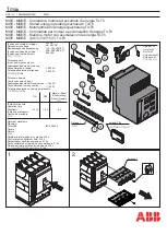
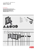
Figure 1.8 Wiring Diagram for 520MCV with Ground
Alarm/Power Supply Module
This message could also indicate that the trip unit
is out of calibration and should be replaced at the
earliest opportunity.
1.8 UL, CSA and CE Recognition
The Digitrip 520V and 520MCV Trip Units are a UL
®
(Underwriters Laboratories, Inc.)
Recognized Component
under File E146559 for use in Type VCP-T, VCP-TR and
Type T-VAC, T-VACR Medium Voltage Circuit Breakers.
They have also been tested by the Canadian Standards
Association (CSA).
This Digitrip 520V and 520MCV have also passed the IEC
947-2 test program which includes radiated and conducted
emissions testing. As a result, all units carry the CE mark.
2.0 GENERAL DESCRIPTION of VCP-T, VCP-TR or
T-VAC, T-VACR CIRCUIT BREAKERS
2.1 General
The circuit breakers are tripped automatically on overload
and fault current conditions by the combined action of
three components:
1. The sensors, which measure the current level
2. The Digitrip Trip Unit, which provides a tripping signal to
the Trip Actuator, when current and time delay settings
are exceeded.
3. The low-energy Trip Actuator, which actually trips the
circuit breaker.
This arrangement provides a very flexible system, covering
a wide range of tripping characteristics described by the
time-current curves referenced in Section 9.2.