background image

SPI9000 Inverter Unit FI9 – FI14 User Manual

MN04004002E 

For more information visit: 

www.EatonElectrical.com

2-5

September 2006

Figure 2-5: Installation Space

B

2

B

A

C

FI9/FI10

FI12

FI13

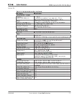
Summary of Contents for Cutler-Hammer SPI9000

Page 1: ...MN04004002E For more information visit www EatonElectrical com SPI9000 Inverter Unit FI9 FI14 User Manual September 2006 Supersedes April 2006...

Page 2: ......

Page 3: ...GE OF TRADE ARE MADE REGARDING THE INFORMATION RECOMMENDATIONS AND DESCRIPTIONS CONTAINED HEREIN In no event will Eaton Electrical Inc be responsible to the purchaser or user in contract in tort inclu...

Page 4: ...CHAPTER 3 POWER WIRING 3 1 Power Connections 3 9 Installation Instructions 3 15 Frame Sizes 3 16 Cable Installation and the UL Standards 3 17 Cable and Motor Insulation Checks 3 17 CHAPTER 4 CONTROL W...

Page 5: ...5 Option Board A9 Wiring Diagram 4 3 Figure 4 6 Option Board A2 Wiring Diagram 4 3 Figure 4 7 Option Board A3 Wiring Diagram 4 4 Figure 4 8 Galvanic Isolation Barriers 4 5 Figure 4 9 Positive Negative...

Page 6: ...3 9 Table 3 2 Fuses Used in 465 800V DC Inverters 3 9 Table 3 3 Fuses Used in 640 1100V DC Inverters 3 10 Table 3 4 Cable Sizes for 380 500V AC 3 11 Table 3 5 Terminal Sizes for 380 500V AC 3 12 Tabl...

Page 7: ...an result in minor to moderate injury or serious damage to the product The situation described in the CAUTION may if not avoided lead to serious results Important safety measures are described in CAUT...

Page 8: ...into contact with this voltage is extremely dangerous and may cause death or severe injury The control unit is isolated from mains potential WARNING The supply and motor terminals are live when the in...

Page 9: ...en open the cover before this time has expired CAUTION Do not perform any voltage withstand tests on any part of inverter There is a certain procedure according to which the tests shall be performed I...

Page 10: ...ay not function properly If fault current protective switches are used they need to be tested with ground fault currents present during possible fault situations Motor and Equipment Safety CAUTION Bef...

Page 11: ...surance company or the carrier If the delivery does not correspond to your order contact the supplier immediately Table 1 1 FI9 FI14 Inverter Unit Catalog Numbering System S P I 0 1 6 A 0 4 A 1 N 1 Ke...

Page 12: ...ommend cleaning the heatsink with compressed air whenever necessary The cooling fan can easily be changed if required It may also be necessary to check the tightening torques of terminals at certain i...

Page 13: ...keypad a PC can be used to control the inverter if connected through a similar cable The basic control interface and the parameters the Basic Application are easy to use If a more versatile interface...

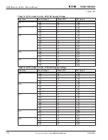
Page 14: ...ess than the factory default Nominal Current Loadability Motor Shaft Power Frame Dimensions and Weight W x H x D Wt in in lbs mm kg Low High Max Current IS 675V DC Supply Rated Cont Current IL A 10 Ov...

Page 15: ...n the factory default Nominal Current Loadability Motor Shaft Power Frame Dimensions and Weight W x H x D Wt in in lbs mm kg Low High 930V DC Supply Rated Cont Current IL A 10 Over load Current A Rate...

Page 16: ...ting Torque IS for two seconds torque motor dependent Peak Current IS for 2 seconds every 20 seconds Output Frequency 0 320 Hz 7200 Hz special Frequency Resolution Application dependent Control Charac...

Page 17: ...Ri 200k 10V to 10V joystick control Resolution 0 1 Accuracy 1 Analog input current 0 4 20 mA Ri 250 differential Digital inputs 6 Positive or negative logic 18 30V DC Auxiliary voltage 24V 15 max 250...

Page 18: ...89 350 FI10 385 9 454 460 9 542 520 9 613 FI12 590 9 695 650 9 766 730 91 870 820 91 977 920 91 1096 1030 91 1227 FI13 1150 91 1370 1300 91 1549 1450 91 1727 FI14 1770 92 2132 2150 92 2590 2700 92 325...

Page 19: ...Tables 2 5 and 2 6 Also make sure that the mounting plane is relatively even The inverter is fixed with four screws or bolts depending on the unit size The following pages show the dimensions for the...

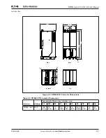
Page 20: ...006 Figure 2 2 SPI9000 FI10 Inverter Dimensions Table 2 2 SPI9000 FI10 Inverter Dimensions Inverters Voltage Approximate Dimensions in Inches mm W1 W2 H1 H2 H3 D1 D2 D3 Dia SPI208 325 480V 575V 9 4 23...

Page 21: ...gure 2 3 SPI9000 FI12 Inverter Dimensions Table 2 3 SPI9000 FI12 Inverter Dimensions Inverters Voltage Approximate Dimensions in Inches mm W1 W2 W3 H1 H2 H3 D1 D2 D3 Dia SPI385 650 480V 18 8 478 7 9 2...

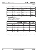
Page 22: ...for free space Table 2 5 If several units are mounted on top of each other the required free space equals 2 C see Figure 2 5 Moreover the outlet air used for cooling by the lower unit must be directed...

Page 23: ...SPI9000 Inverter Unit FI9 FI14 User Manual MN04004002E For more information visit www EatonElectrical com 2 5 September 2006 Figure 2 5 Installation Space B2 B A C FI9 FI10 FI12 FI13...

Page 24: ...20 3 9 100 FI10 380 500V 525 690V 7 9 200 79 20 3 9 100 FI12 380 500V 525 690V 7 9 200 79 20 0 3 9 100 FI13 380 500V 525 690V 7 9 200 79 20 0 3 9 100 FI14 380 500V 525 690V 7 9 200 79 20 0 3 9 100 A f...

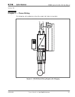
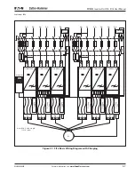
Page 25: ...sit www EatonElectrical com 3 1 September 2006 Chapter 3 Power Wiring The following wiring diagrams show the supply and motor connections Figure 3 1 FI9 FI10 Basic Wiring Diagram with Charging DC Exte...

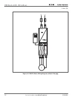
Page 26: ...FI14 User Manual 3 2 For more information visit www EatonElectrical com MN04004002E September 2006 Figure 3 2 FI9 FI10 Basic Wiring Diagram without Charging DC Controller X10 X15 X9 H1 H7 Cooling Fan...

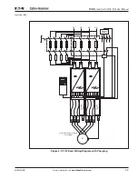
Page 27: ...nElectrical com 3 3 September 2006 Figure 3 3 FI12 Basic Wiring Diagram with Charging Controller Note Min Cable Length 131 2 40m X10 Cooling Fan H1 7 H903 H900 X9 X15 X10 H1 7 H903 H900 X9 X15 B U V M...

Page 28: ...lectrical com MN04004002E September 2006 Figure 3 4 FI12 Basic Wiring Diagram without Charging Controller Note Min Cable Length 131 2 40m DC X10 Cooling Fan DC H1 7 H903 H900 X9 X15 X10 H1 7 H903 H900...

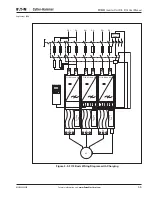
Page 29: ...tonElectrical com 3 5 September 2006 Figure 3 5 FI13 Basic Wiring Diagram with Charging Controller Cooling Fan X10 H1 7 H903 H900 X9 X15 B U M FI 10 Module U B Cooling Fan DC DC DC DC B V FI 10 Module...

Page 30: ...ion visit www EatonElectrical com MN04004002E September 2006 Figure 3 6 FI13 Basic Wiring Diagram without Charging Controller Cooling Fan X10 H1 7 X9 X15 U M FI 10 Module U Cooling Fan V FI 10 Module...

Page 31: ...ing Controller Cooling Fan X10 H1 7 H903 H900 X9 X15 B U FI 10 Module U B Cooling Fan DC DC DC DC B V FI 10 Module V B DC DC Cooling Fan B W PE FI 10 Module W B External Supply Note Min Cable Length 1...

Page 32: ...ram without Charging Controller Cooling Fan X10 H1 7 H903 H900 X9 X15 U FI 10 Module U Cooling Fan V FI 10 Module V Cooling Fan W PE FI 10 Module W Cooling Fan X10 H1 7 H903 H900 X9 X15 U M FI 10 Modu...

Page 33: ...nverter to the motor In any other case ask the factory for more information Table 3 1 Cable Types Required to Meet Standards Fuses 465 800V DC Inverters Table 3 2 Fuses Used in 465 800V DC Inverters C...

Page 34: ...V Fuse In A No of Fuses 100 FI9 170M4199 1SHT 1250 400 2 125 FI9 170M4199 3SHT 1250 400 2 144 FI9 170M4199 3SHT 1250 400 2 170 FI9 170M4199 3SHT 1250 400 2 208 FI10 170M6305 3SHT 1250 700 2 261 FI10 1...

Page 35: ...Cu 3x150 70 Al 3x240Al 72Cu 205 261 3x 1x24 Cu 3x185 95 Al 2x 3x120 70 245 300 6x 1x24 Cu 2x 3x120 70 Al 2x 3x185Al 57Cu 300 FI10 385 5x40 Cu 2x 3x120 70 Al 2x 3x185Al 57Cu 385 460 5x40 Cu 2x 3x150 7...

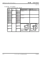
Page 36: ...l Sizes for 380 500V AC Nominal Current Frame IL A Approximate Dimensions in Inches mm DC Supply Terminal Motor Cable Terminal 140 FI9 170 PE M8 x 25 170 205 205 261 245 300 300 FI10 385 PE M8 x 25 38...

Page 37: ...x95 50 Al 3x120 70 144 170 2x 1x24 Cu 3x95 50 Al 3x120 70 170 208 2x 1x24 Cu 3150 70 Al 3x240Al 72Cu 208 FI10 261 3x 1x24 Cu 3x185 95 Al 2x 3x95Al 29Cu 261 325 5x40 Cu 2x 3x95 50 Al 2x 3x150Al 41Cu 32...

Page 38: ...ions in Inches mm DC Supply Terminal Motor Cable Terminal 100 FI9 125 125 144 144 170 170 208 208 FI10 261 261 325 325 385 325 416 385 FI12 460 460 502 502 590 590 650 650 750 650 820 820 FI13 920 920...

Page 39: ...tances 4 If cable insulation checks are needed see Page 3 17 5 Connect the cables Strip the motor and DC supply cables Remove the screws of the cable protection plate Do not open the cover of the powe...

Page 40: ...more information visit www EatonElectrical com MN04004002E September 2006 Frame Sizes Inverter Frame FI13 Protection Class IP00 Inverter Frame FI12 Protection Class IP00 Inverter Frame FI9 Protection...

Page 41: ...stance of the motor cable between each phase conductor as well as between each phase conductor and the protective ground conductor The insulation resistance must be 1M 2 DC supply cable insulation che...

Page 42: ...SPI9000 Inverter Unit FI9 FI14 User Manual 3 18 For more information visit www EatonElectrical com MN04004002E September 2006...

Page 43: ...g The control unit of the inverter consists of the control board and option boards see Figures 4 1 and 4 2 connected to the five slot connectors A to E on the control board The control board is connec...

Page 44: ...externally 24V by connecting the external power source to bidirectional terminal 6 see Figure 4 5 This voltage is sufficient for parameter setting and for keeping the fieldbus active Note If the 24V i...

Page 45: ...24V GND 24V GND 0 4 20 mA RL 500 V 48V I 50 mA Input Reference Voltage Input Reference Current Indicates Connections for Inverted Signals Control Voltage Output Basic I O Board A9 AIA1 10Vref 24Vout...

Page 46: ...nal wire size is 14 AWG for the relay terminals and 16 AWG for other terminals You can find the tightening torques of the option board terminals in Table 4 1 Table 4 1 Tightening Torques of Option Boa...

Page 47: ...See Figure 4 8 The digital inputs are galvanically isolated from the I O ground the relay outputs are also double isolated from each other at 300V AC EN 50178 Figure 4 8 Galvanic Isolation Barriers R...

Page 48: ...directional 24V auxiliary voltage 15 maximum current 250 mA all boards total 150 mA from single board Can also be used as external power backup for the control unit and fieldbus 7 GND I O ground Groun...

Page 49: ...ommon inputs CMA CMB can be either internal or external Figure 4 9 Positive Negative Logic Positive logic 24V is the active signal Input is active when the switch is closed Negative logic 0V is the ac...

Page 50: ...r to better suit his needs by selecting certain positions for the jumpers on the OPTA9 board The positions of the jumpers determine the signal type of analogue and digital inputs On the A9 basic board...

Page 51: ...lock X1 AI1 Mode AI1 Mode 0 20mA Current Input A B C D A B C D A B C D AI1 Mode Voltage Input 0 10V AI1 Mode Voltage Input 0 10V Differential AI1 Mode Voltage Input 10 10V A B C D Jumper Block X6 AO1...

Page 52: ...SPI9000 Inverter Unit FI9 FI14 User Manual 4 10 For more information visit www EatonElectrical com MN04004002E September 2006...

Page 53: ...ee indicators for the control place I O term Keypad BusComm There are also three Status Indicator LEDs green green red see Page 5 3 The control information i e the menu number description of the menu...

Page 54: ...Indicator Description Motor is running Blinks when the stop command is given but the frequency is still ramping down Indicates the direction of motor rotation Indicates that the drive is not running...

Page 55: ...es Figure 5 2 Keypad Pushbuttons Indicator Description Lights up when the AC power is connected to the drive Simultaneously the drive status indicator READY is lit up Lights up when the drive is runni...

Page 56: ...This button is used to browse up through the main menu and pages of different submenus Edit values This button is used to browse down through the main menu and pages of different submenus Edit values...

Page 57: ...he user can navigate in the main menu with the Browser buttons up and down The desired submenu can be entered from the main menu with the menu buttons When there still are pages to enter under the cur...

Page 58: ...Parameters P1 P3 Language English Change value System Menu S1 S9 Output frequency 13 95 Hz Monitor V1 V15 No editing 11 Output phase T1 T7 Fault history H1 H3 Operation days 17 11 Output phase T1 F T7...

Page 59: ...tion M1 is visible on the first line of the display Figure 5 5 shows how to browse through the monitored values The monitored signals carry the indication V and they are listed in Table 5 6 The values...

Page 60: ...come in handy when a relatively greater or smaller value than that on the display is desired Confirm the change with the ENTER button The value will not change unless the ENTER button is pressed Press...

Page 61: ...ctive Figure 5 6 Parameter Value Change Procedure Keypad Control Menu M3 In the Keypad Control Menu you can choose the control place edit the frequency reference and change the direction of the motor...

Page 62: ...Button Right The options can then be browsed with the Browser buttons Select the desired control place with the ENTER button See Figure 5 7 Figure 5 7 Selection of Control Place Keypad Reference The k...

Page 63: ...e location indication M4 is visible on the first line of the keypad display When a fault brings the inverter to a stop the location indication F1 the fault code a short description of the fault and th...

Page 64: ...Type Symbol Meaning A Alarm This type of fault is a sign of an unusual operating condition It does not cause the drive to stop nor does it require any special actions The A fault remains in the displ...

Page 65: ...f the inverter can store a maximum of 30 faults in order of appearance The number of faults currently in the fault history is shown on the value line of the main page H1 H The order of the faults is i...

Page 66: ...first line of the keypad display The controls associated with the general use of the inverter such as application selection customized parameter sets or information about the hardware and software ar...

Page 67: ...set 2 S6 3 2 Load to keypad All parameters S6 3 3 Load from keypad All parameters All but motor parameters Application parameters P6 3 4 Parameter backup Yes No Yes S6 4 Parameter comparison S6 5 Safe...

Page 68: ...ers T6 8 2 1 MWh counter kWh T6 8 2 2 Clear MWh counter T6 8 2 3 Operation day counter T6 8 2 4 Operation hour counter T6 8 2 5 Clear operation hour counter S6 8 3 Software information S6 8 3 1 Softwa...

Page 69: ...tion Selection The user can select the desired application on the Application selection page S6 2 To enter the page press Menu Button Right on the first page of the System menu To change the applicati...

Page 70: ...eters included in the application On the Parameter Sets page S6 3 1 press Menu Button Right to enter the edit mode The text LoadFactDef begins to blink and you can confirm the loading of factory defau...

Page 71: ...is activated control keypad makes a copy of the parameters of the presently used application When applications are changed you will be asked if you wish the parameters of the new application to be upl...

Page 72: ...ine If any of the parameter values differ from those of Set1 the number of the deviations is displayed together with symbol P for example P1 P5 five deviating values By pressing Menu Button Right once...

Page 73: ...mber between 1 and 65535 Note You can also set the password by digits In the edit mode push Menu Button Right again and another zero appears on the display Set ones first To set the tens press Menu Bu...

Page 74: ...17 Parameter Locking Start Up Wizard P6 5 3 The Start Up Wizard facilitates the commissioning of the inverter If active the Start Up Wizard prompts the operator for the language and application of hi...

Page 75: ...ngs Submenu Default Page P6 6 1 Here you can set the location page to which the display automatically moves when the Timeout Time see below has expired or the power is switched on to the keypad If the...

Page 76: ...by pressing Menu Button Right Set the desired timeout time and confirm it with the ENTER button You can return to the previous menu at any time by pressing Menu Button Left Figure 5 22 Timeout Time S...

Page 77: ...n internal brake resistor the default value of this parameter is Connected However if it is necessary to increase braking capacity by installing an external brake resistor or if the internal brake res...

Page 78: ...4 Fan Control Function HMI Acknowledge Timeout P6 7 3 This function allows the user to change the timeout of the HMI acknowledgement time The inverter waits for the HMI acknowledgment in accordance wi...

Page 79: ...after the next start up System info In the System info submenu S6 8 you can find inverter related hardware and software information You can enter the System info submenu by pressing Menu Button Right...

Page 80: ...nter Example When you want to reset the operation counters see Figure 5 26 Figure 5 26 Counter Reset Software S6 8 3 The Software information page includes information on the following inverter softwa...

Page 81: ...e applications loaded into the inverter Locate the desired application with the Browser buttons and then enter the Information pages with Menu Button Right Use the Browser buttons to see the different...

Page 82: ...eason the text no conn is displayed For more information see Chapter 4 For more information on expander board related parameters see Page 5 30 Figure 5 28 Expander Board Information Menus Expander Boa...

Page 83: ...l application related functions See the application manual for more information Code Parameter Min Max Default Cust Selections P7 1 1 1 AI1 mode 1 5 3 1 0 to 20 mA 2 4 to 20 mA 3 0 to 10V 4 2 to 10V 5...

Page 84: ...SPI9000 Inverter Unit FI9 FI14 User Manual 5 32 For more information visit www EatonElectrical com MN04004002E September 2006...

Page 85: ...are isolated from the mains potential However the relay outputs and other I O terminals may have a dangerous control voltage present even when the inverter is disconnected from DC supply Do not make...

Page 86: ...Stop switches connected to the I O terminals are in the Stop position 6 Connect the inverter to DC supply 7 Set the parameters of group 1 according to the requirements of your application see applica...

Page 87: ...safely prior to performing it Inform your co workers of the tests Switch off the DC supply voltage and wait until the drive has stopped as advised on Page 6 1 Safety Precautions Connect the motor cab...

Page 88: ...SPI9000 Inverter Unit FI9 FI14 User Manual 6 4 For more information visit www EatonElectrical com MN04004002E September 2006...

Page 89: ...age exceeded the defined limits Deceleration time too short High overvoltage spikes in supply Set the deceleration time longer Add a brake chopper or brake resistor 3 Ground Fault Current measurement...

Page 90: ...mperature is over 90 C Overtemperature warning is issued when the heatsink temperature exceeds 85 C Check the correct amount and flow of cooling air Check the heatsink for dust Check the ambient tempe...

Page 91: ...39 Device Removed Option board removed Drive removed Reset Note No fault time data record 40 Device Unknown Unknown option board or drive Contact your Cutler Hammer distributor 41 IGBT Temperature IGB...

Page 92: ...52 Keypad communication Fault There is no connection between the control keypad and the inverter Check the keypad connection and keypad cable 53 Fieldbus Fault The data connection between the fieldbu...

Page 93: ...SPI9000 Inverter Unit FI9 FI14 User Manual MN04004002E For more information visit www EatonElectrical com A 5 September 2006...

Page 94: ...SPI9000 Inverter Unit FI9 FI14 User Manual A 6 For more information visit www EatonElectrical com MN04004002E September 2006...

Page 95: ......

Page 96: ...Powerware Durant Heinemann Holec and MEM which globally serve the changing needs of the industrial utility light commercial residential and OEM markets For more information visit www EatonElectrical...

Reviews: