background image

10

EATON CORPORATION Cutler-Hammer

 Pow-R-Command 750 LCD Display  Instruction Leaflet IL01412018E  Effective: February 2009

Troubleshooting Guide / FAQ

General Troubleshooting

Symptom 1:

 The text on the LCD display is not visible/legible. There 

is a blue backlight, but the text is washed out.

Cause: 

The contrast on the LCD needs to be adjusted.

Solution: 

Press the 

BACK

 key multiple times to ensure that you are 

on the very first screen of the LCD. Press the 

SEL

 key one time. 

Press and hold the 

UP

 arrow. The contrast should begin to lighten. 

You can make the contrast darker by pressing and holding the 

DOWN

 arrow. The contrast can also be adjusted from within the 

ADVANCED MENU

.

Symptom 2: 

One or more Smart Breakers are not showing up in 

CONFIGURE GROUPS.

Causes:

1. Subnetwork wiring from controller to each BCB in master and 

expansion panelboards is not properly pulled/terminated.

2. BCBs are not properly addressed via DIP switches on each BCB.

3. Smart Breaker has not properly been connected to BCB 

breaker port.

4. Breakers have not properly been discovered.

Solution:

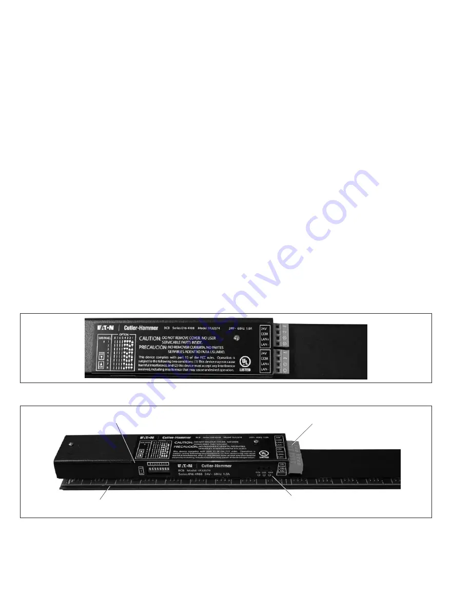
Step 1: Make sure all subnetwork wiring from controller to each BCB 
(including expansion panelboards) is properly terminated. (See 

Figure 2

.)

Step 2: Ensure that each BCB is properly addressed via the DIP 
switches on each BCB. (See 

Figure 3

.)

Step 3: Make sure that each Smart Breaker is properly terminated 
onto each BCB Breaker Port. Each Smart Breaker has a 4-pin connec-
tor that slides onto each 4-pin breaker port on the BCB. It is very easy 
to misalign this connection.

Step 4: Discover breakers. Please reference the LCD Quick Start 
Guide for complete details on how to properly discover all Smart 
Breakers.

Note: 

If Smart Breaker(s) still do not show up in configure groups 

after completing these steps, please call the PRC Technical Support 
Line at 1-888-252-6286, Option 3.

Documents to Reference:

1. Instruction Leaflet (IL01412012E).

Symptom 3:

 After completing the above steps, one or more Smart 

Breakers are not responding to issued commands.

Note: 

Make sure all the above steps have been completed before 

proceeding.

Causes: 

1. The Smart Breaker(s) has/have been Overridden.

2. The black primary handle to the breaker is in the OFF position.

Definition of Overridden: Breaker is taken “out of service” or taken 
out of normal operation. This means that the Smart Breaker will not 
follow any issued commands. The breaker must be restored and put 
back into service/normal operation to follow issued commands.

Solution:

1. Take a look at the status LEDs on front of the controller. They are 

located next to the power switch to the controller. There will be 
three LEDS. The top LED represents the power to the controller.  
This LED is red and should be constantly ON. The middle LED is 
the “override” LED. If any one of the Smart Breakers are overrid-
den, this LED will be lit. This LED is green. The bottom LED is 
the network LED. It will blink RED during normal operation. 

If the middle LED is lit/green, this means that the Smart 
Breaker(s) is/are overridden and need to be restored back into 
service. From the MAIN MENU of the LCD, scroll down and 
select BYPASS LOADS ON/OFF (this should be the last option on 
the MAIN MENU). Next, scroll down and select CLEAR BYPASS.

2. If it is safe to energize the load connected to each Smart Breaker, 

ensure that the black primary handle to the breaker is in the ON 
position. The Smart Breaker will not properly respond to issued 
commands when the black primary handle is in the OFF position.

FIGURE 2. 

FIGURE 3. 

Subnetwork LAN
Address DIP Switches

BCB Breaker Port/
Termination

Subnetwork LAN/
Power Terminations

RUN, LAN and POWER 
Status LEDs

Summary of Contents for Cutler-Hammer Pow-R-Command 750

Page 1: ... SEL Generally BACK is used to cancel a selection or to move back up through the menu hierarchy UP DOWN are used to scroll through selections on a menu or to change values SEL is used to choose a menu item or to enter a setting Some menu screens will have an arrow symbol in the lower right corner This indicates there are additional menu items for this screen Use the UP DOWN keys to scroll down to ...

Page 2: ...pdf for fur ther directions on how to address the BCBs and properly connect them to the PRC750 controller 4 Discover Breakers Discover breakers is located in the main menu The first time the Pow R Command Control Unit is powered up it automatically discovers the breakers that are connected to it through the Breaker Control Buses BCBs This assumes that the addresses on the BCBs have been set correc...

Page 3: ...06 30 SET 07 00 Note Sunrise sunset calculations lose accuracy outside the 62 to 62 range Hit SEL to move to the longitude setting Use UP DOWN to set the longitude value in degrees The longitude range is 180 Alaska to 180 Western Pacific Hit SEL to move to the TIMEZONE setting Use UP DOWN to set the TIMEZONE value in hours The TIMEZONE range is 12 hours west of GMT to 12 hours east of GMT After se...

Page 4: ...Maint NO Input DI 1 OFF Delay 00 00 Up Down SEL to Change Press BACK when Done The Input Select screen displays the type of input the input that is associated and the Exit time delay Use the UP DOWN to highlight TYPE and press Select An input type list is displayed The list of input types extends beyond one page Use UP DOWN to scroll through the list and highlight the correct switch type Hit Selec...

Page 5: ...sired group in this case A Use UP to turn the group ON and DOWN to turn the group OFF Verify that the correct set of breakers is turned ON and OFF with the group If not repeat Step 6A Configure Breaker Group A Associate Loads With the Group If there is an associated input for this group turn the group OFF again with the COMMAND GROUPS screen Use the actual input switch motion detector etc to trip ...

Page 6: ...K when done PICK SCHEDULE DAYS Weekdays____________ Weekends Clear All Days Pick specific days Yes No SMTWTFSH ENTER SCHEDULE DETAIL For GROUP B Days Weekday Start time 12 00 AM End time 12 00 PM Clear Schedule Press BACK when done Use UP DOWN to advance the hours column to the correct hourly starting time Hit SEL to move to the minutes column Use UP DOWN to advance the minutes column to the corre...

Page 7: ...r module three actions are available for the respective group a Stay Stay in the present state last recorded before loss of communication with the master unit b On Change to the ON state when loss of communication with the master unit occurs c Off Change to the OFF state when loss of communication with the master unit occurs 7 Run Cycle Displays the running count of the number of times the group h...

Page 8: ...0 character description describing the respective breaker b Name Field The name field allows the user to modify the default 4 character load identifier used with the respective breaker c Address Field Each unit can have a unique address numbered from 1 to 120 for networking purposes This field allows the user to assign an address to the unit d Bypass ON Bypasses ALL loads ON e Bypass ON Bypasses A...

Page 9: ...f breakers per panelboard 9 18 30 or 42 where 42 circuit is the default a Panelboard List 1 8 1 Panelboard Configuration a Panelboard Number Allows the user to specify a unique numerical address to associate with the panelboard b Panelboard Name Allows the user to alter the default 4 character identifier for the panelboard c Panelboard Type Allows the user to pick the configuration of the panelboa...

Page 10: ... show up in configure groups after completing these steps please call the PRC Technical Support Line at 1 888 252 6286 Option 3 Documents to Reference 1 Instruction Leaflet IL01412012E Symptom 3 After completing the above steps one or more Smart Breakers are not responding to issued commands Note Make sure all the above steps have been completed before proceeding Causes 1 The Smart Breaker s has h...

Page 11: ...correct amount 2 Controllers are available in various voltages Check the trans former label for the correct input voltage 3 Press the reset on the transformer there will be a noticeable click if it resets The transformer may have tripped if the trip state continues after resets this is a sign of other issues Make sure no wires are pinched or shorted coming from the controller If none found please ...

Page 12: ... Location Latitude 90 to 90 __ degrees__ Longitude 180 to 180 __degrees__ Time zone 12hrs to 12hrs __hrs 4 Breaker Groups Mark the groups each circuit is part of Copy this page as needed for additional panelboards GROUPS CIRCUIT A B C D E F G H I J K L M N O P CIRCUIT A B C D E F G H I J K L M N O P 1 22 2 23 3 24 4 25 5 26 6 27 7 28 8 29 9 30 10 31 11 32 12 33 13 34 14 35 15 36 16 37 17 38 18 39 ...

Page 13: ...__ __ AM PM Group Weekends Weekdays S M T W T F S H Start__ __ AM PM End __ __ AM PM Group Weekends Weekdays S M T W T F S H Start__ __ AM PM End __ __ AM PM Group Weekends Weekdays S M T W T F S H Start__ __ AM PM End __ __ AM PM Group Weekends Weekdays S M T W T F S H Start__ __ AM PM End __ __ AM PM Group Weekends Weekdays S M T W T F S H Start__ __ AM PM End __ __ AM PM Group Weekends Weekdays...

Page 14: ...14 EATON CORPORATION Cutler Hammer Pow R Command 750 LCD Display Instruction Leaflet IL01412018E Effective February 2009 Notes ...

Page 15: ...EATON CORPORATION Cutler Hammer Pow R Command 750 LCD Display Instruction Leaflet IL01412018E Copyright 2009 15 Notes ...

Page 16: ...E Z7732 February 2009 Eaton Corporation Electrical Group 1000 Cherrington Parkway Moon Township PA 15108 United States 877 ETN CARE 877 386 2273 Eaton com PowerChain Management Pow R Command Cutler Hammer and Smart Breakers are registered trademarks and trademarks of Eaton Corporation ...

Reviews: