IB01602007E
For more information visit: www.cutler-hammer.eaton.com
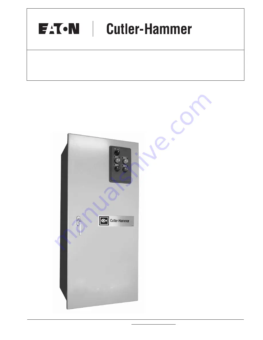
O&M Manual for Non-AutomaticTransfer Switches (30 – 1200 Amperes)
Instruction Bulletin
New Information
Page 1: ...IB01602007E For more information visit www cutler hammer eaton com O M Manual for Non Automatic Transfer Switches 30 1200 Amperes Instruction Bulletin New Information...
Page 2: ...PROVIDED ON THE NAMEPLATE A TYPICAL EQUIPMENT NAMEPLATE IS SHOWN IN FIGURE 1 Automatic Transfer Switch Cat No NTVEKDB0300X54 06 03 GO No Item 1 1 of 1 E Poles 3 Amps 300 Volt 480 Phase 3 Hertz 60 Wir...
Page 3: ...ic Panel Door Mounted 11 11 Charger Mounting Dimensions in Inches mm 12 12 Typical NEMA Type 1 Enclosure Door Closed 13 13 Vertical Design Power Panel Mounting Reference in Inches mm 15 14 Vertical De...
Page 4: ...power from one of these two sources In the event that power is lost from the normal power source the transfer switch transfers the load to the secondary emergency power source Trans fer can be automat...
Page 5: ...r Switch was designed with installation ease and simplified maintenance in mind Three main panels comprise the automatic transfer switch design Power Panel Voltage Selection Panel Logic Panel Each pan...
Page 6: ...tch Electrically Operated Switching Device Orientation V Vertical 1 H Horizontal 2 Control Panel E Electromechanical Number of Poles 2 Two 3 Three 4 Four Ampere Rating 30A 0030 70A 0070 100A 0100 150A...
Page 7: ...option which includes specially designed cleats transfer switches have a seismic capability which exceeds the worst case Zone 4 required levels per both the Uniform Building CodeT and the California B...
Page 8: ...otectors over the indicating light panel and operating handle A heavy duty cardboard lid covers the entire opening The shipment is secured and further protected with shrink wrap Do not discard the pac...
Page 9: ...d automatic transfer switch encompasses all transfer switch equipment possibilities it is the only specific type that will be discussed in this section Figure 6 Typical Vertical Design Power Panel Unm...
Page 10: ...s from being closed simultaneously The load side contacts of each switching device are joined with a bus bar assembly to form a common load terminal location either top or bottom Figure 14 Horizontall...
Page 11: ...ges taps from 208 600 Vac satisfy any required application voltage A quick change capability from one voltage to another is provided by a small disconnect plug 3 4 Logic Panel The logic panel provides...
Page 12: ...12 volts D 24 volts When supplied the battery charger is provided in a separate wall mounted enclosure Figure 11 Separate instructions and wiring information are provided with the charger for installa...
Page 13: ...switch equipment enclosed in a NEMA 1 enclosure is UL listed for application In addition Cutler Hammer Transfer Switches are listed in File E38116 by Underwriters Laboratories Inc under Standard UL 10...
Page 14: ...Carefully remove all packing material from the transfer switch at the mounting location Even though an equipment inspection was made when the equipment was received make another careful inspection of...
Page 15: ...the two upper mounting bolts in the mounting surface Step 3 Gently lift the enclosure and guide the elongated holes in the upper mounting flange over the upper mounting bolts but do not completely tig...
Page 16: ...ill facilitate re installation of the power panel Step 4 Remove the operating mechanism from the front of the power panel by removing the six bolts holding the mechanism in position The molded case sw...
Page 17: ...glass poly ester phase barriers are in place and positioned properly in the grooves provided When making any bolted connection to the bus comply with the torque requirements as outlined in Table 3 Ta...
Page 18: ...nting holes in the power panel with the pre tapped inserts in the rear of the enclosure Step 10 With the power panel held securely against the back of the enclosure replace and tighten the four mounti...
Page 19: ...identified on the label affixed to the unit immediately adjacent to the lugs Step 7 Make necessary connections of options using wiring diagrams and Quick Start Guide supplied with the unit Table 4 Tr...
Page 20: ...vertical design transfer switch is furnished with a multi tap Voltage Selection Panel to the right of the power panel Seven front accessible taps from 208 to 600 Vac are provided Figure 9 A small disc...
Page 21: ...zes a mechanical mechanism with a manual operating handle Figure 15 The manual operating handle can be used to create the rota tional motion required to open and close the main contacts through a rigi...
Page 22: ...d to a transfer motor Figure 16 A slide pin engaging a pivot in the rotating lever converts rotary motion to linear motion To operate breaker manually or if the breaker trips unplug P3 from S3 to disc...
Page 23: ...pened or closed electrically There is however no intelligence circuit associated with this design Electrical operation is accomplished by adding a motor and required circuitry to the manual mechanism...
Page 24: ...mpany 6 Basic description of situation as it exists 7 Any results of problem solving steps taken and or readings taken 6 2 1 Transfer Switch Appears Inoperative Step 1 Verify that all plugs and socket...
Page 25: ...ake certain that any accessory control power is switched off by disconnecting all logic plugs B Inspect structure area for safety hazards or potential maintenance problems Inspect area especially wher...
Page 26: ...OF DEALING OR USAGE OF TRADE ARE MADE REGARDING THE INFORMATION RECOMMENDATIONS AND DESCRIPTIONS CONTAINED HEREIN In no event will the Cutler Hammer business be responsible to the purchaser or user in...
Page 27: ...2007E For more information visit www cutler hammer eaton com Instruction Bulletin Effective June 2003 Page 27 O M Manual for Non Automatic Transfer Switches 30 1200Amperes This page intentionally left...
Page 28: ...Transfer Switches 30 1200Amperes 2003 Eaton Corporation All Rights Reserved Printed in USA Publication No IB01602007E June 2003 Eaton Corporation Cutler Hammer business unit 1000 Cherrington Parkway M...