Eaton Cutler Hammer MN05001002E Installation Manual Download Page 6


Intelligent Technologies QCPort System Install Manual 

November 2005  


MN05001002E 

For more information visit 

www.eatonelectrical.com


Page 

6


Interconnectivity Using QCPort 

Introducing QCPort 

The interface demands on control devices continues to increase at a rapid pace.  An 
intelligent control device requires connection to configuration and monitoring tools, 
operator interfaces, and other peripheral devices, as well as the option to connect to a 
variety of industrial fieldbusses.  At the same time, the intelligent devices continue to 
shrink in size and cost, forcing distribution of the field connections that once were native 
on the devices.  

QCPort is a flexible interface port that integrates the many connectivity needs of the 
intelligent device into a single device port for the means of control, setup, and 
configuration.  The integration of these capabilities provides interface options that are 
powerful and cost effective.  In addition to the interface functionality of QCPort, care has 
been taken to insure that systems that connect via QCPort are simple to configure, 
connect, and maintain. 

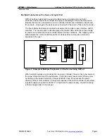
QCPort Physical Characteristics  

In an effort to use existing proven technology, QCPort uses the RS485 physical layer.  
This physical layer is common to many industrial communication interfaces and has a 
long and proven track record within industrial applications.  QCPort is a four-wire system 
where there is an A and B for signal and a +DC and Ground for device power.  
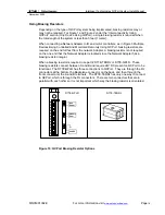
Depending on the type of device interconnect and the distance between devices, there 
are many choices for the type of interconnect physical media; these choices will be 
discussed further in the manual.  

Summary of Contents for Cutler Hammer MN05001002E

Page 1: ...MN05001002E C For more information visit www eatonelectrical com Intelligent Technologies QCPort System Install Manual November 2005 Supercedes November 2004...

Page 2: ...f this control equipment must satisfy themselves that all necessary steps have been taken to assure that each application and use meets all performance and safety requirements including any applicable...

Page 3: ...of the product National Electric Code Warning Do not install or perform maintenance on the QCPort system while the system is energized Death or severe personal injury as well as damage to other equipm...

Page 4: ...A QCPORT SYSTEM 11 QCPort Backplane 11 QCPort Interconnect Cable 12 DAISY CHAIN 14 TRUNK DROP 14 PHYSICAL PLACEMENT 15 USING BIASING RESISTORS 16 APPLICATION EXAMPLE 17 PLANNING A QCPORT INTERCONNECT...

Page 5: ...3 Example of Remote Connection Using QCPort 9 Figure 4 QCPort Backplane Connector 11 Figure 5 6 Pin QCPort Linear Connector 11 Figure 6 QCPort Interconnect Cable 12 Figure 7 QCPort Powered Interconne...

Page 6: ...intelligent device into a single device port for the means of control setup and configuration The integration of these capabilities provides interface options that are powerful and cost effective In a...

Page 7: ...er interface and operator stations Figure 1 Example of One Device Using QCPort The interconnect supplied with the operator interface connects the operator interface to the motor controller This connec...

Page 8: ...modules The input module is used to apply a hard wired HOA while the output module is used to annunciate the motor controller status and trip conditions The mapping of the data between the motor contr...

Page 9: ...required refer to Locating a Power Supply later in this manual Along with the power supply sizing physical media restrictions must be followed This includes the length of the interconnects type of in...

Page 10: ...tor control devices A slave only communicates when it is communicated to thus eliminating collisions Since there are no unscheduled communications in a Master Slave system the scan time of a QCPort sy...

Page 11: ...feet 300 meters 230Kbaud In this case special care has to be taken to size the power supply correctly for the distance QCPort Backplane The QCPort backplane provides a convenient way to connect the Ne...

Page 12: ...rt Interconnect cable is ordered from the factory at preconfigured standard lengths QCPort devices provide two QCPort interconnect cable plug connections that are in parallel so that the devices can b...

Page 13: ...ong Run Cable Connection Long Run Cable Recommended Manufacturers Table 1 Manufacturers and Part Numbers for Long Run Cables Manufacturer Part Number Belden 82842 Plenum Rated Belden 9842 Non Plenum R...

Page 14: ...han 10 feet 3 meters are required between devices there are other methods that include using a long run cable and connectors Methods of connection include using QCPort Interconnect Cable QCPort Backpl...

Page 15: ...rt Backplane Long Run or any combination of the three Physical Placement When planning the connection care should be taken as to the physically placement of the devices Considerations include Grouping...

Page 16: ...hest from the network Adapter A biasing resistor is not required on the one end that the Network Adapter is located since the Network Adapter has a biasing resistor integral When a biasing resistor is...

Page 17: ...and the change from the backplane to the QCPort Interconnect cable is performed there as well When powering the QCPort system the power supply that provides power to the starters is the same power su...

Page 18: ...to NEC and CE Code limits respectively Use a power supply that has its own current limit protection Make sure you derate the supply for temperature using the manufacturer s guidelines Provide fuse pr...

Page 19: ...t be between 18 and 28V DC Locating a Power Supply The QCPort interconnect system allows several options for supplying power as outlined in this section To determine which option meets your needs cons...

Page 20: ...e location Warning If you use more than one power supply all of them should be attached to the same earth ground Ground the G conductor at only one place at the power supply that is closest to the phy...

Page 21: ...wer supply for the expected temperature using the manufacturer s guidelines Use a power supply that has its own current limit protection Adjusting the Configuration When the sections have a voltage dr...

Page 22: ...drop allowed This is the total cable system voltage drop of 5 00V minus 0 35V reserved for drop line voltage drop Nt The number of taps between the device being evaluated and the power supply For exam...

Page 23: ...have to be relocated Example 2 End Connected Power Supply 1 Sum up the currents QCPort Interconnect system 0 1 0 4 0 3 0 8 A OK since 10 feet allows 1 0A 2 Find the voltages for each node using the e...

Page 24: ...0 105 Nt x 0 005 x In 4 65V Device 1 9 x 0 105 3 x 0 005 x 0 2 0 19V Device 2 6 x 0 105 2 x 0 005 x 0 3 0 19V Device 3 3 x 0 105 1 x 0 005 x 0 1 0 03V Device 4 0 x 0 105 1 x 0 005 x 1 0 0 00V Device 5...

Page 25: ...QCPort System Install Manual November 2005 MN05001002E For more information visit www eatonelectrical com Page 25 Troubleshooting and Maintenance Refer to the selected device manuals for more detailed...

Page 26: ...QPLR provides for screw lugs for connection to industrial RS485 cable Example of Long Run Cable One Power Supply End Connected The following example uses the full calculation method to determine the...

Page 27: ...Run SUM L n x 0 0045 N t x 0 005 x I n 4 65V Device 1 18 x 0 021 1 x 0 005 x 1 0 0 383V Device 2 36 x 0 021 2 x 0 005 x 0 5 0 383V Device 3 43 x 0 021 3 x 0 005 x 0 4 0 367V Device 4 95 x 0 021 4 x 0...

Page 28: ...001002E For more information visit www eatonelectrical com Page 28 Technical Support For additional information on this product Please call our Customer Support Center at 1 800 356 1243 For service or...

Page 29: ...eds of the industrial utility light commercial residential and OEM markets For more information visit www eatonelectrical com Eaton Corporation is a global diversified industrial manufacturer with 200...

Reviews: