Intelligent Technologies QCPort System Install Manual
November 2005
MN05001002E
For more information visit
www.eatonelectrical.com
Page
9
Multiple Devices Being Controlled And Monitored Remotely Using QCPort
When an industrial fieldbus adapter is used within a system, the adapter will act as a
subscanner presenting the QCPort devices as IO to the industrial fieldbus. This allows
the QCPort devices to be monitored, controlled, and configured from a remote location.
For this type of application, a power supply will be required; it can be the same power
supply that is used for the motor controllers.
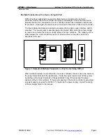
Figure 3: Example of Remote Connection Using QCPort
Since a power supply sizing is required, refer to “Locating a Power Supply” later in this
manual. Along with the power supply sizing, physical media restrictions must be
followed. This includes the length of the interconnects, type of interconnects, and the
power capabilities for the interconnects.
This type of application requires some configuration. The Group IDs for the QCPort
devices need to be set to unique IDs, the adapter requires an address configuration, and
then the mapping feature needs to be invoked to map the QCPort data to the industrial
fieldbus. None of these configuration requirements require a software tool. If advanced
configuration of the QCPort devices is required, then a software tool or a QCPort user
interface will be required. For information on configuration of the QCPort devices, refer to
the user manual for those devices.
DeviceNet
IT. 24V DC
Power Supply
IT. EM Starters and D77B-QSNAPs


