PUB 50411
D64RP18 SERIES B1 DIGITAL GROUND FAULT RELAY
Revision 2
May, 2005
Page 6
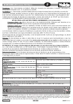
TABLE 1 – DIPSWITCH SETTINGS
In the table below ‘R’ denotes right and ‘L’ denotes left.
Switch
Function
Set to
Meaning
1 2 3
Ground fault trip current limit R L L
R L R
R R L
R R R
♦
L L L
L L R
L R L
L R R
30 mA
120 mA
210 mA
300 mA
600 mA
2.4 Amps
4.2 Amps
6.0 Amps
4
Trip time delay
R
♦
L
Instantaneous (20 ms)
500 ms
♦
FACTORY SETTING
2.2.1
GROUND FAULT TRIP CURRENT LEVEL - DIPSWITCHES 1, 2, & 3
The ground fault TRIP LEVEL range is 30 mA - 6 Amps. Table 1 provides a listing of the eight TRIP
LEVEL settings, which can be made on DIPswitches 1, 2, & 3.
As indicated in the General Description, it is recommended that the ground fault TRIP LEVEL setting
be kept as close to the charging current as possible. This will provide maximum safety for operating
personnel and equipment protection. On resistance grounded systems, the TRIP LEVEL setting
should be set lower than 20% of the Neutral Grounding Resistor let-through current.
If the measured ground fault current exceeds the TRIP LEVEL setting, the output relay changes state
after the pre-selected TRIP DELAY time.
2.2.2
GROUND FAULT TRIP DELAY TIME – DIPSWITCH 4
The ground fault TRIP DELAY time can be set at Instantaneous (20 ms) or 500 ms with DIPswitch 4.
The TRIP DELAY time begins when the ground fault trip level setting is reached or is exceeded.
Set the ground fault TRIP DELAY time to provide the desired delay before the output relay changes
state when the ground fault TRIP LEVEL setting is reached or exceeded.
The setting should be selected to co-ordinate with other ground-fault devices connected on the same
transformer secondary: set shorter than upstream devices; set longer than downstream devices. If no
other ground-fault devices are connected, set for the shortest time.
2.3
OUTPUT RELAY OPERATING MODE
Referring to the Glossary of Terms, determine if NON-FAILSAFE or PULSED TRIP AUTO RESET
operation of the output relay is required.
For Non-Failsafe operation leave terminals R1 and R2 open or connect a N.O. momentary contact
TEST/RESET button to these terminals.
For Pulsed Trip Auto Reset operation install a jumper between terminals R1 and R2 or connect a N.C.
momentary contact TEST button to these terminals.