


2
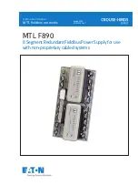
INM F890 Rev 1
segment is automatically maintained when single or redundant Power Modules are
fitted. The F890-CA carrier is equipped with connectors that will accept an F809F
diagnostic module. The module continuously monitors the performance of each of the
eight fieldbus segments, providing information on the network health.
Each Power Module has indicator LEDs to show both its status and that of the eight
segments under power. In normal operation, each green ‘Segment’ LED is lit, showing
that the segment is powered. If a segment is shorted, or its voltage is below the rated
output, its LED is extinguished, and the red ‘Alarm’ LED is lit. Redundant 24V DC (nom.)
input power is connected to the F890-CA carrier using two-part pluggable connectors.
Field wiring connections are available with either pluggable screw terminals (F890-PS)
or pluggable spring clamp terminals (F890-PC).
3
COMPONENTS AND ACCESSORIES
Product part numbers and their descriptions are given to the right .
F801
8 Segment Power Module: 21 .5V, 350mA
F802
8 Segment Power Module: 28V, 500mA
F809F
8 Segment Fieldbus Diagnostic Module
F890-CA-P*
Carrier
F890-P*
F890-CA-P* and two F801 modules
F890-2-P*
F890-CA-P* and two F802 modules
F890-P*-NR
F890-CA-P* and one F801 module
F890-2-P*-NR F890-CA-P* and one F802 module
F800-BLK
Blanking Module included with –NR systems
* =
S – Pluggable Screw Terminal Connectors
C – Pluggable Spring Clamp Connectors


