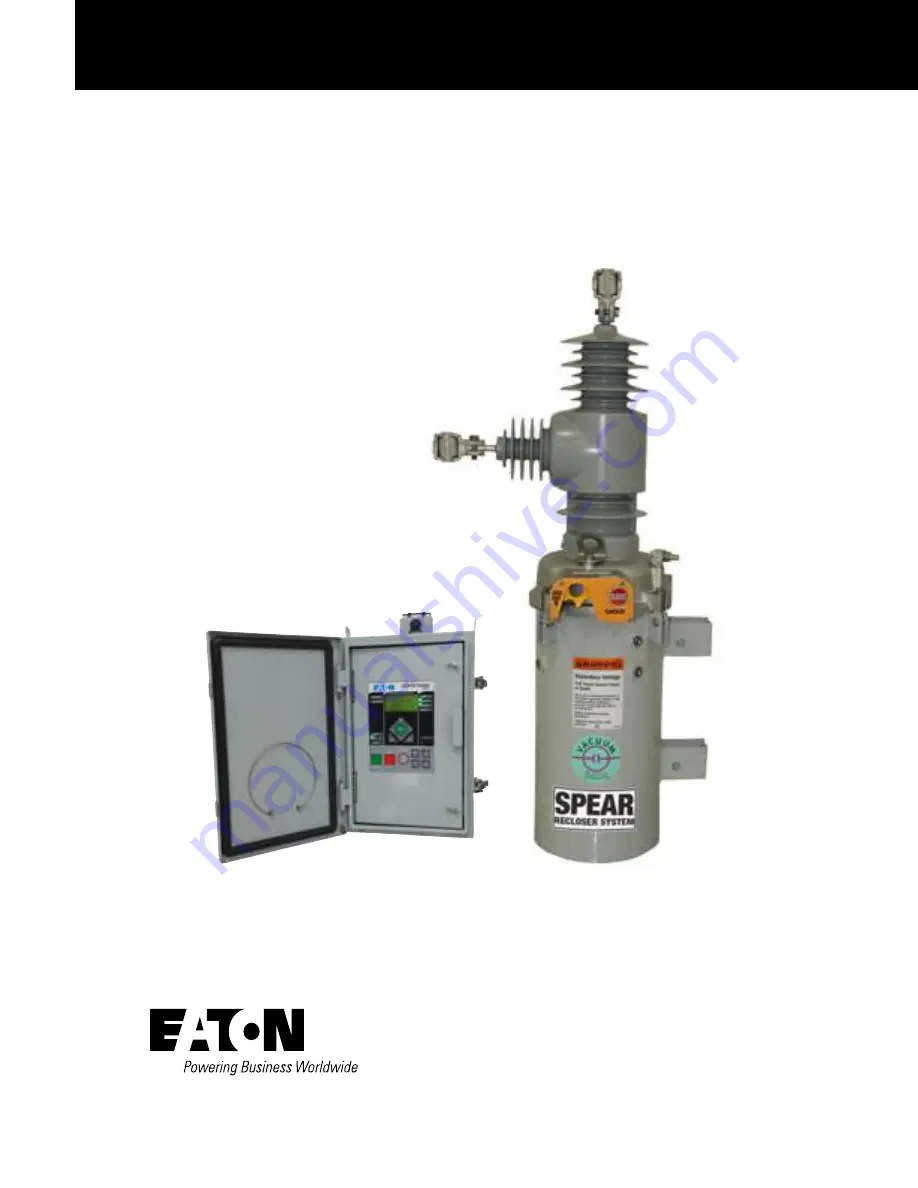
SPEAR™ Single-Phase Recloser System Installation and Operation
Instructions
COOPER POWER
SERIES
Reclosers
MN280048EN
Effective June 2016Supersedes S280-101-1 (May 2015)
Page 1: ...SPEAR Single Phase Recloser System Installation and Operation Instructions COOPER POWER SERIES Reclosers MN280048EN Effective June 2016 Supersedes S280 101 1 May 2015...
Page 2: ...ULAR PURPOSE OR MERCHANTABILITY OTHER THAN THOSE SPECIFICALLY SET OUT IN ANY EXISTING CONTRACT BETWEEN THE PARTIES ANY SUCH CONTRACT STATES THE ENTIRE OBLIGATION OF EATON THE CONTENTS OF THIS DOCUMENT...
Page 3: ...2 Battery monitoring 2 ProView NXG software 3 SPEAR single phase recloser system description 3 Recloser description 3 Control description 3 Theory of operation 4 Control front panel 4 Control features...
Page 4: ...r receptacles 29 Cable locking sleeves 29 Automation accessory packages 29 Communication board accessories 30 Recloser accessories 31 Terminal options 31 Mounting hangers 31 Recloser service informati...
Page 5: ...high voltage lines and equipment and support our Safety For Life mission Safety information DANGER Hazardous voltage Contact with hazardous voltage will cause death or severe personal injury Follow a...
Page 6: ...recommends transporting SPEAR single phase reclosers in the closed position to maximize the operational performance of the unit IMPORTANT If stored outdoors the product must be removed from the cardbo...
Page 7: ...trol shuts down automatically upon detection of low battery voltage below 21 VDC for 60 seconds Refer to the Control testing section for additional battery monitoring information Control programming s...
Page 8: ...sive system protection functionality Analysis tools include sequence of events recording and data profiler Metering functions include demand and instantaneous current instantaneous voltage and power f...
Page 9: ...The following chain of events occurs for an operating sequence of two trips to lockout one trip on TCC1 one trip on TCC2 1 The overcurrent signal is integrated with time on the selected curve for the...
Page 10: ...ft key is used to go up one Menu level The left key is used to move left when editing parameters The right key is used to go down one Menu level The right key is used to move right when editing parame...
Page 11: ...s indicated on the right side of the control Figure 5 Figure 5 DATA PORT ENTER EDIT ESC BATTERY TEST SUPER VISORY OFF NON RECLOSE HOT LINE TAG TRIP OFF LOCKOUT CLOSE SPEAR Single Phase Recloser Contro...
Page 12: ...er is required for the TRIP button to issue a command to the recloser CLOSE membrane pushbutton When pressed the CLOSE pushbutton Figure 7 returns the control to the initial or home sequence position...
Page 13: ...tion is restricted to the operator panel Operational data and metering information are available while the control is in the SUPERVISORY OFF position NON RECLOSE The control is operating in a non recl...
Page 14: ...al and number of operations to lockout for each protection profile Cold Load Pickup also includes TCC Multipliers TCC Adders Minimum Response Time and High Current Lockout Also direct values not multi...
Page 15: ...eration is performed The delay is programmable from 0 to 60 seconds in 1 second increments A programmed delay value can be overridden for immediate closing by pressing the CLOSE button a second time A...
Page 16: ...V 23 0 kV V 100 100 100 100 100 100 100 100 100 Continuous Current Ratings A 400 630 800 400 630 800 400 630 800 Sym Interrupting Current A 8 000 12 500 12 500 8 000 12 500 12 500 8 000 12 500 12 500...
Page 17: ...on 15 kV 27 kV 38 kV Terminal to Terminal 40 9 in 1039 mm 40 9 in 1039 mm 40 9 in 1039 mm Lower Terminal to Ground 26 5 in 673 mm 30 5 in 775 mm 37 5 in 953 mm Table 6 Dimensions B C D 15 kV 34 5 in 8...
Page 18: ...Personal injury Sheds on epoxy encapsulation have sharp edges Wear protective gloves when handling the unit Failure to do so can result in cuts and abrasions T258 1 WARNING Falling equipment Use the...
Page 19: ...VIEW AS SHIPPED LOAD SOURCE VIEW WITH HEAD ROTATED 90 NOTES 1 CUSTOMER TO PROVIDE ARRESTER AS REQUIRED 2 ARRESTER SHOWN IS A COOPER UltraSIL HOUSED VariSTAR SURGE ARRESTER 15 kV 14 68 373 14 68 373 1...
Page 20: ...bolt to release clamp tension Failure to remove tension between the clamp and the interrupter stud prior to rotating the terminal will damage the encapsulated interrupter assembly resulting in equipm...
Page 21: ...r reconnection of the control cable to the control T311 1 3 Open the source and load disconnect switches 4 Remove the control AC sensing and power connections from the control using a separate disconn...
Page 22: ...that provide the energy to operate the mechanism To open the main contacts the trip coil is pulsed with electrical current which cancels the magnetic field A compression spring in the center of the co...
Page 23: ...ngs have been properly programmed and verified Refer to the programming information for this control Failure to comply can result in control and recloser misoperation equipment damage and personal inj...
Page 24: ...r SPEAR single phase recloser 1111 Duty cycle factor is Value x 105 Mounting the control Mount the SPEAR single phase recloser control in a convenient accessible location Mounting dimensions are provi...
Page 25: ...ECEPTACLES LATCHES WITH PADLOCK PROVISIONS 1 13 LIFTING LUG 10 63 MOUNTING CHANNELS 1 12 9 84 PROVISIONS FOR UP TO 5 8 MOUNTING HARDWARE GROUND LUG FOR 4 TO 14 SOLID OR STRANDED WIRE 12 01 VENT OPENIN...
Page 26: ...routed within 8 inches of their corresponding ground During a surge a potential of approximately 1 5 kV per foot can develop in the conductors Differences between conductor and ground path lengths can...
Page 27: ...ess WARNING Hazardous voltage Recloser and control must be solidly grounded Follow all locally approved procedures and safety practices when grounding this equipment Improper grounding can result in c...
Page 28: ...e SPEAR single phase recloser control is connected to incoming line power Note N An 8 A hr lead acid battery will fully charge in 24 hours or less at 25 C The charger includes a temperature compensate...
Page 29: ...ONTROL POWER INPUT R2 BLK WHT B A CUSTOMER WIRING 120 240 VAC CUSTOMER CONTROL POWER INPUT NEUTRAL HOT TO R1 J 015 015 OPTIONAL FACTORY ACCESSORY WIRING Neutral must be connected to Earth ground exter...
Page 30: ...G 120 240 VAC CUSTOMER CONTROL POWER INPUT NEUTRAL HOT TO R1 J 015 015 C BRAID 120 240 VAC CUSTOMER CONTROL POWER INPUT R2 OPTIONAL FACTORY ACCESSORY WIRING Neutral must be connected to Earth ground e...
Page 31: ...inputs terminal block on the back panel as shown in Figure 24 The two Contact I O outputs are Form C relay contacts and are of non latching type Refer to Table 10 for output fusing recommendations Not...
Page 32: ...state 10 9 8 7 Customer connections to Contact I O module with shielding and surge protection I O functionality shown is factory default for the module Figure 25 10 5 2 1 0 5 0 2 0 1 10 20 50 100 200...
Page 33: ...mately five seconds If the battery is OK the PASS message will appear If the battery is not OK one of these messages will appear ATTENTION 1 indicates Battery Test Trouble ATTENTION 2 indicates Batter...
Page 34: ...r supply is backed up by the control batteries in the SPEAR single phase recloser control cabinet and will continue to provide power to connected accessories under loss of AC line power to the reclose...
Page 35: ...Serial communication card The communication accessory expansion bay concept offers high versatility with respect to communication medium and protocol support Additional accessories are being continuo...
Page 36: ...recommends terminal connection to copper wires to optimize the electrical connection Aluminum cables may produce aluminum oxide sufficient to compromise the electrical connections Anti oxide coatings...
Page 37: ...d casting and mechanism are removed from the tank the center of gravity changes Secure an additional strap to the horizontal side arm to prevent the module from tipping 3 Loosen bolts that secure head...
Page 38: ...Information S280 90 1 Vacuum Interrupter WithstandTest Voltage Ratings Information for further information G109 2 The following tests should be applied to the SPEAR single phase recloser Closed contac...
Page 39: ...4 Inspect module for damage to the terminals Remove any damaged terminals and replace 5 Inspect module for damage to the module conductor rods 0 63 diameter threaded rods on top and side of module for...
Page 40: ...ater 7 1 3 2 VTC 240 K P2 2 MS3 NC Actuator Circuit Board P2 3 5 6 8 1 1 MS2 NC SPEAR single phase recloser internal wiring Figure 35 VTC 28 V dc 53 V dc 53 V Common Common 28 V dc Chassis Shield MS1...
Page 41: ...to the BATTERY menu item and press the ENTER button Code 081 Battery Voltage and Current will be displayed VBat XX XX Volts IBat X XX Amps B Press the down arrow button to scroll to the Test Battery c...
Page 42: ...control then remove control cable at control end before disconnecting from recloser end T312 3 1 Disconnect the 24 V control battery 2 Disconnect control cable from control 3 Remove control AC sensin...
Page 43: ...Recloser Control Tester Operating Instructions for proper setup and use of the MET Tester Figure 40 Type MET electronic recloser control tester Note N Setting the S2 switch of the MET Tester to the CA...
Page 44: ...splayed VBat XX XX Volts IBat X XX Amps Table 17 Control battery bench testing and replacement information Control type Battery Battery catalog part Voltage Type Amp Hour Bench test load condition for...
Page 45: ...he battery has reached a full charge This process can take up to 24 hours Refer to Table 18 for additional battery charging accessories Table 18 Battery charging accessories Description Catalog number...
Page 46: ...s and battery bracket Additional information CAUTION This equipment requires routine inspection and maintenance to ensure proper operation If it is not maintained it can fail to operate properly Impro...
Page 47: ...ited States Eaton com cooperpowerseries 2016 Eaton All Rights Reserved Printed in USA Publication No MN280048EN June 2016 KA20480750 REV00 Eaton is a registered trademark All trademarks are property o...