3
Disc Valve Hydraulic Motor
10 000 Series
Geroler Motors—Two Speed
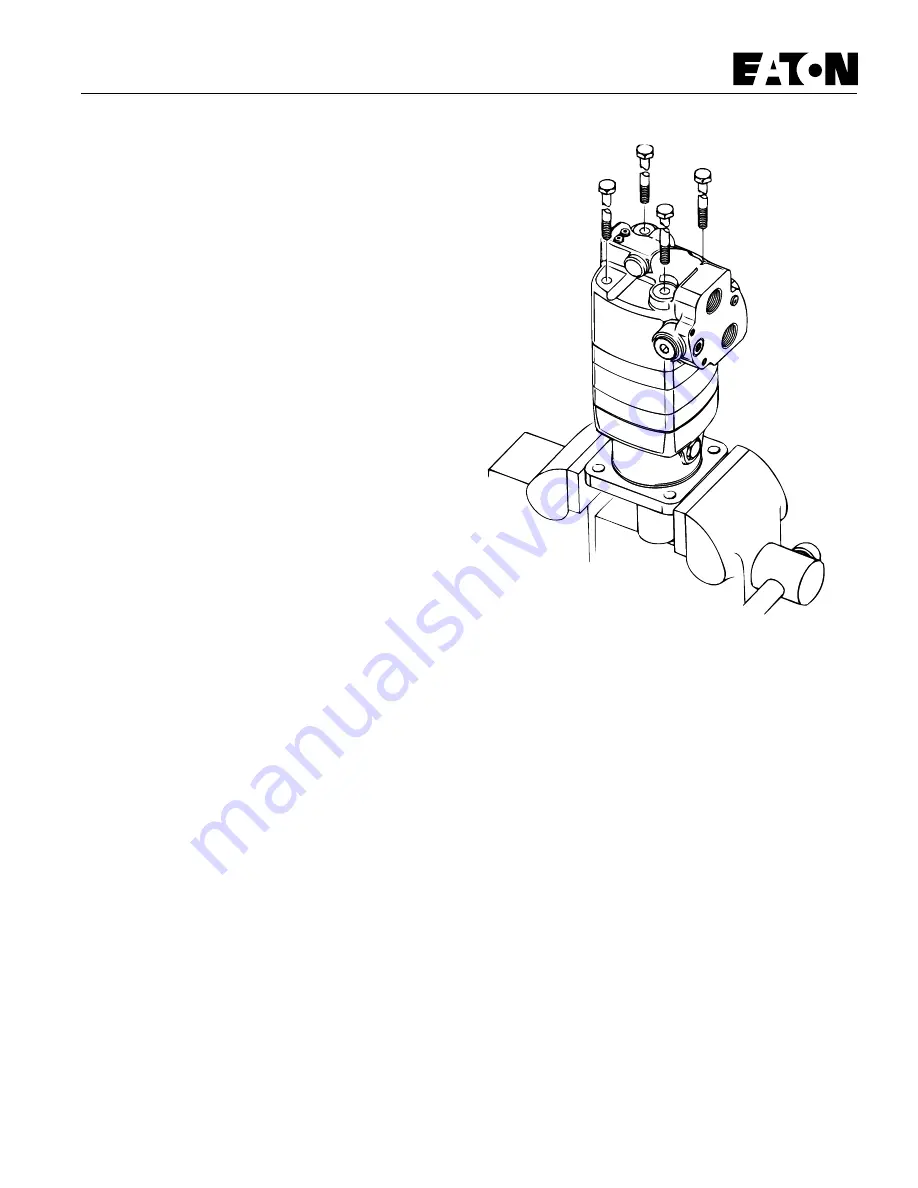
Figure 1
Tools Required:
- Torque Wrench, 165 Nm [120 lb-ft] * capacity
- 15/16, 1, and 1–1/4 inch sockets
- 5/32, 3/16, 5/16, and 5/8 inch hex keys
- 300 mm to 450 mm [12 to 16 inch] breaker bar
- Small blade screwdriver, 150 to 200 mm [6 to 8 inch] long
- Plastic or rubber hammer
Special Tools:
- Small internal bearing puller, sliding hammer type
- Output shaft sleeve
* Inch equivalents given in [brackets].
Disassembly
Cleanliness is extremely important when repairing hydraulic motors.
Work in a clean area. Before disconnecting the oil lines thoroughly
clean the port area of the motor. After the oil lines have been
disconnected, plug the motor’s ports to prevent dirt from entering.
Clean the exterior of the motor with a wire brush. Check the keyway
and chamfered area of the output shaft and remove any nicks, burrs,
or sharp edges that could damage the shaft seals during reassembly.
Drain the oil from the motor before beginning disassembly.
Note: On the standard and wheel motors the output shaft seal and dust
seal can be changed without completely disassembling the motor.
Steps 23 through 41 describe shaft and dust seal replacement. If
complete disassembly is planned, both the shaft seal kit and motor seal
kit will be needed. Refer to parts list 6-131 for seal kit part numbers.
1 Place the motor in a vise with the output shaft down. Clamp on the
motor’s mounting flange as shown in Figure 1. Protect the mounting
flange with soft vise jaws, wood, or hard rubber. Use just enough
clamping force to hold the motor securely during repairs. Excessive
force will distort the motor housing.
Note: Even though the motor is not shown in a vise in all the
drawings, it is recommended that the motor be kept clamped in a
vise during repairs.
2 Remove the four hex head bolts from the motor.


