15
Mounting- and Operating Instruction CEAG DualGuard-S
40071860347 January 2020 www.ceag.de
6 Assembly and installation of the DualGuard-S
Mains connection
Connecting the mains power supply
Power is supplied via the general mains supply or via the
Batterys of a battery bank (battery cabinet or rack).
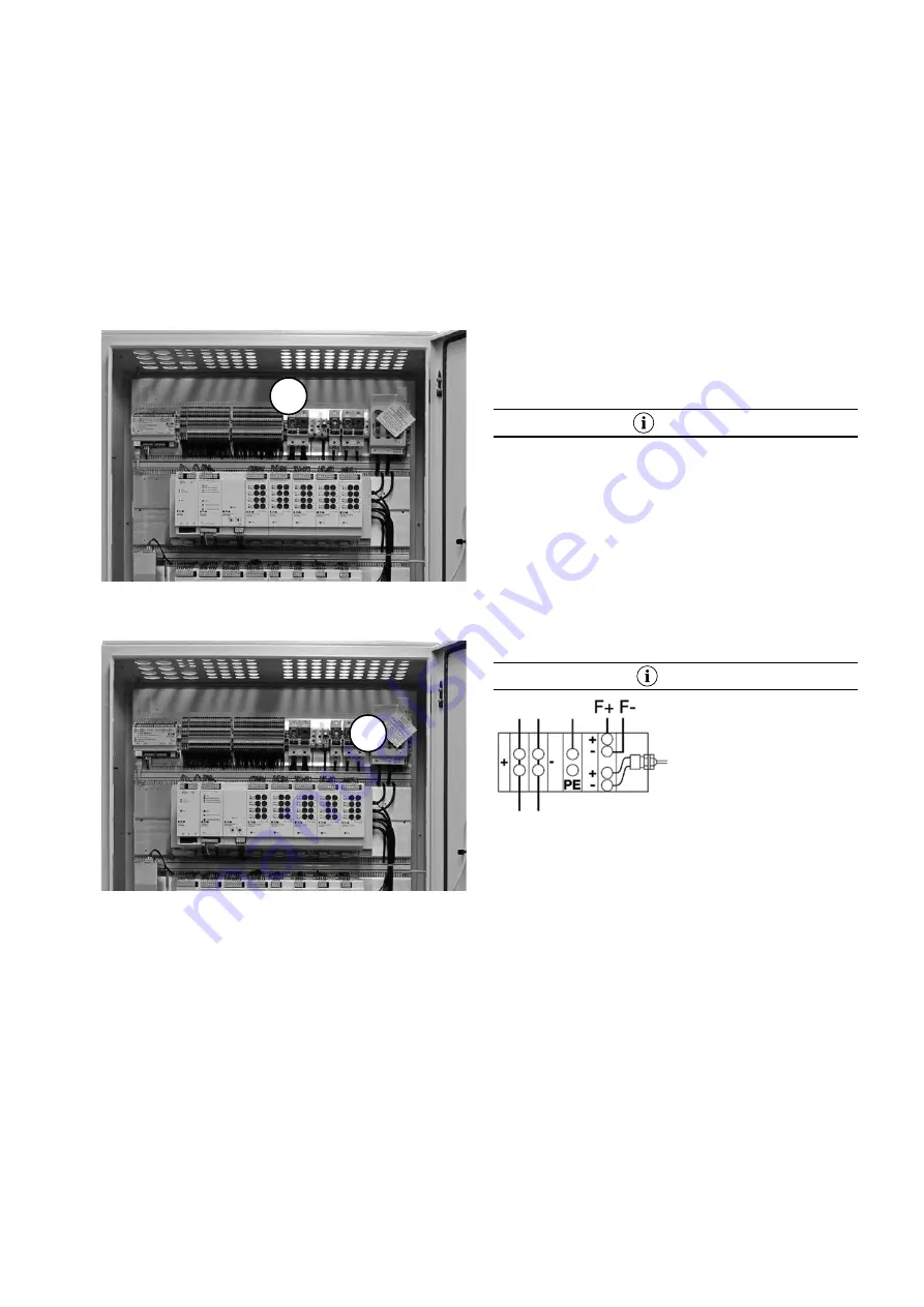
Example DualGuard-S 12C:
1 phase mains connection to load disconnector (1) and PE
terminal
1-phase mains connection of a substation to load discon-
nector (1) and PE.
Make sure that the mains cable is disconnected. Connect
the 230V mains cable to the fuse isolator (1).
Mains connection of sub-stations
If the substations are to be supplied via the power supply of
the associated DualGuard-S system, an outgoing distributor
for three 1-phase or one 3-phase power supply must be
available for connection.
• Make sure that the system and the supply lines are dis-
connected and secured!
• Connect the protective conductor to the PE terminal block.
• Connect the neutral conductor to the N-terminal block.
• Connect the L-conductor to the terminals of the outgoing
distributor.
NOTE!
To make work easier, outgoing distributors can be removed
from the busbar to the front when the lock on the upper
housing wall is released. Once the outgoing cables have
been connected, the outgoing distributor can be placed back
on the busbar with slight pressure and snapped into place.
Battery Supply Connections
Please observe the battery manufacturer‘s data sheets
enclosed with the CEAG battery banks!
Observe the legal regulations and rules which apply at the
place of operation of the emergency lighting system!
NOTE
CEAG battery cabinets are
equipped as standard with a
cabinet terminal block (see
illustration) on which the con-
necting cables (+/-) for the
battery power supply and a
temperature sensor (F+/F-)
are connected. The PE con-
nection is used to protect live parts of the battery cabinet.
In the case of battery racks and battery cabinets, the con-
necting cables to the end poles of the interconnected Batte-
rys are not included in the scope of delivery. In the case of
battery racks, the terminal block is not included in the scope
of delivery.
CEAG recommends the installation of a battery supply dis-
tributor with circuit breaker, string monitoring and fuses for
the battery circuit (see „Installation Instructions for Battery
Power Distributors“), which enables safe disconnection
of the terminals for the connecting cables leading to the
DualGuard-S control cabinet.
The battery connection cables (for the DualGuard-S control
cabinet and its substations) must be laid in accordance with
DIN VDE 0100T520 to be protected against groanding and
short circuits!
Ensure that the cables have a conductor cross-section that
is suitable for the expected current flows to the connected
loads.
Only one temperature sensor (F+ / F-) and up to four battery
1
1


