6
Instruction Leaflet
IL019226EN
Effective October 2018
C-HRG technical information
and adjustment procedure
EATON
www.eaton.com
Yearly (or more if significant dirt accumulation is noted)
•
Clean equipment: in addition to monthly checks, after first
de-energizing the equipment, remove the cover over the resistor
compartment. Check for heat and note dirt accumulation.
Compare to last observations. Using a good quality industrial
vacuum cleaner with a soft brush attachment, clean dirt from
resistors, vents, and the cabinet
•
Inspect for contamination: inspect assembly for contamination
from airborne pollutants (oil mist, lint, and so on). The accumulation
of significant amounts may indicate the need for specialized
cleaning procedures, and/or the need to take measures to keep
the contaminants away from the grounding assembly
•
Inspect for overheating: darkening of copper ground bus and
moderate discoloration of resistor tubes and terminal bands is
normal. Painted surfaces adjacent to the resistors will darken
somewhat over time, but should not appear blackened or burnt.
Check that all wiring is routed away from resistors and that no
wiring passes over resistors
•
Check wiring: check that all wiring connections to resistors and
ground bus are secure
•
Clean control compartment: use vacuum cleaner to clean dirt
accumulation from control compartment. Be very careful not to
dislodge wiring
•
Replace covers: replace all covers and all cover hardware. Return
to service as directed
Fuse replacement
DANGER
FIRE AND SHOCK HAZARD!
MAY CAUSE DEATH, BODILY INJURY, OR EQUIPMENT DAMAGE.
TURN CONTROL DISCONNECT OFF BEFORE SERVICING FUSES.
ANY REPLACEMENT FUSE MUST BE THE SAME RATING AS ORIGINAL.
A control disconnect switch is provided on the line side of all fuses.
Turn disconnect off before servicing fuses.
All primary fuses are selected to allow application on power systems
with an available fault current of 200 kA rms at 600 Vac, maximum.
If any fuse must be replaced, be certain that only an identically-rated,
UL
T
listed fuse is installed. If a substandard or underrated fuse is
used, it may rupture violently, causing burns, electrical shock, and/or
substantial equipment damage. If the original fuse is not available or
its markings not legible, refer to label adjacent to fuseblock or to the
schematic for this unit.
Adjustment procedure
WARNING
HIGH VOLTAGE!
MAY CAUSE DEATH, BODILY INJURY, OR EQUIPMENT DAMAGE.
TURN OFF POWER AT THE SOURCE BEFORE WORKING INSIDE.
Before attempting any maintenance, open, tag, and lock out the
primary devices supplying this equipment. Verify that no voltage is
present in this equipment using calibrated testers that are known to
be operating correctly.
The resistor assembly is rated to operate at 375 °C at full load.
Approach it with due caution, especially if a fault condition has
recently occurred. Even when it is hot enough to cause a serious
burn, the resistor assembly may not appear hot!
Resistor taps
CAUTION
HIGH TEMPERATURES!
MAY CAUSE SERIOUS BURNS.
ALLOW RESISTOR ASSEMBLY TO COOL DOWN BEFORE SERVICING.
THE RESISTOR TAP SETTING WILL DETERMINE THE AMOUNT
OF GROUND RETURN CURRENT THAT A SYSTEM WILL
ALLOW AND/OR WHETHER THE C-HRG WILL FUNCTION
PROPERLY. IMPROPER RESISTOR TAP SETTING MAY RESULT
IN EQUIPMENT DAMAGE/MALFUNCTION.
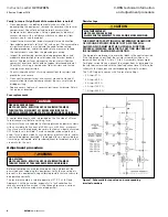
The tap points are brought to a terminal block in the control section.
If the tap jumper is omitted, the resistor assembly will be at its
lowest current rating (1 A for a 1 A to 5 A assembly, for example).
For higher current levels, connect the jumper from its base point to
the tap terminal marked with the required current level. Refer to the
schematic for tap values and corresponding terminal numbers.
The C-HRG typically comes with five resistor settings:
•
5 A tap—57 Ω
•
4 A tap—69.5 Ω
•
3 A tap—89.5 Ω
•
2 A tap—139.5 Ω
•
1 A tap—264.5 Ω
Figure 1. Schematic for tap value and corresponding
terminal numbers


