14
Technical Data
MN019001EN
Effective November 2015
Bussmann series
PV Combiner box
EATON
www.eaton.com
Monitoring solutions
The following chapter details specific operations and program-
ming parameters of the monitoring system contained within the
combiner box. This chapter contains the list of interface parameters,
the list of available registers with the relevant functions and the
explanation of the advantages and disadvantages of particular
functions.
After applying the supply voltage for about 5 seconds, the manufac-
turer information, then the module name and the software version,
e.g. Eaton, are displayed. Next, the main screen appears.
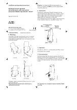
Figure 7. Example display screen
Press the button near the LCD display to view the available infor-
mation on the display. Each press of the button switches to the
display of the next current up to the current in the eighth string;
then further system parameters will be displayed whenever you
press the button: The display does not jump back to the main
screen, the last viewed screen remains displayed. Please note that
in EcoMode the backlight is turned off.
Connecting multiple interfaces
Cables
Use twisted-wire cables, with a screen if possible. Connect all bus
devices as a chain, one behind the other. For the chain configura-
tion the modules have doubled, internally linked through-connec-
tions (top and bottom): You use one bus connection as input, the
other as output to the next bus device. The order of top or bottom
is unimportant here.
Bus wiring for RS-485 or Modbus
Connect the screen of the bus cable flat with screen termi-
nals (no point contact). We recommend that the screens are
only earthed at one point and between the modules are only
connected one to the other.
Bus termination
To prevent signal reflections on the interface lines each section
(bus segment) must be terminated at its physical start and end
with a certain resistance. To do this, a terminating resistance is
connected between the bus lines A and B. The line A is then
connected via a pull-up resistor to +5 V and line B is connected via
a pull-down resistor to 0 V. This cascade of three resistors ensures
interference-free data transmission and defined potentials (voltage
levels) when no data is being transmitted over the bus (the inter-
face). The Type S1 string monitoring units PVCBM-GRI6 already
have these resistors built in. You activate the resistors via both DIP
switches; in this way both bus lines are connected to the resis-
tance circuit: Push the switches in the diagram on the right
upwards. The DIP switches must always be both actuated, i.e.
both set to
on
or both set to
off
.
DIP swTitches for activating the bus termination resistances;
current setting: OFF (down, default setting).