EATON
WSB11206 WCSB Tensioner / Brake with ORB Coolant Ports Installation, Operation and Maintenance Manual E-CLCL-II009-E
August 2015
23
WCSB tensioner / brake with ORB coolant ports
4.5
WC Wear Plate Replacement
Note: As of July, 2014 Wear plate replacement kits for the
24WCSB and 36WCSB are supplied with sealant tape. This is
now the preferred method of sealing the water cavity. Wear plate
replacement kits for the 24WCSB and 36WCSB prior to July, 2014
used Loctite Superflex
®
#596 Sealant. Should the wear plate
replacement kit being used contain Loctite Superflex
®
#596
Sealant, refer to capitalize section 4.5.6 for assembly procedures.
Note: When replacing wear surfaces, it is recommended that
the mating friction material be replaced or machined flat to
ensure good contact between the mating surfaces. See Table 7
for wear limits.
4.5.1 Disassemble WCSB tensioner / brake assembly
per Section 4.3.
4.5.2 Remove the screws and locknuts holding the wear
plates and remove the wear plates. If the wear plates
cannot be easily lifted off, gently tap the O.D. to
break the gasket seal.
Caution
Do not attempt to break the gasket seal by prying
between the wear plate and housing. Damage to the
sealing surfaces may occur.
4.5.3 Inspect the water passages and, if necessary, use a
wire brush to clean them. If re-painting is necessary,
sand blast the water passages and paint the surfaces
with PLASITE
®
Epoxy #9052 Polymine coating. Dry
film thickness should be 8 to 12 mils (0,2 to 0,3 mm).
Be careful not to allow the paint to get into the seal
grooves or onto the face of the support nubs.
Caution
Follow manufacturer's instructions and proper safety
precautions for application of epoxy coatings.
Caution
If nubs are severely corroded, wear plates may
not be properly supported. Replace pressure plate,
reaction plate or end plate, if necessary.
4.5.4
For wear plate replacement kits that contain Loctite
Superflex
®
#596 Sealant proceed to section 4.5.6 for
assembly instructions.
4.5.5 Assembly with Gasket Tape for sizes 24” and 36”
Note: The End Plate (117a), Pressure Plate (14), and Reaction
Plate(s) (31) will be referred to as IRON in the following
paragraphs. Refer to Figure 22 for item number references
shown in parenthesis (#).
4.5.5.1 Preparation and cleaning the IRON:
Ensure that the IRON surface is smooth and free of
paint scale, burrs and corrosion. Thoroughly clean
both the inner and outer lands which will receive the
gasket. Use a solvent based cleaner such as acetone,
mineral spirits or a general-purpose wax / oil / grease
remover turning the wipe until it is free of new dark
debris. Finish the cleaning process by blowing off lint
on the sealing surface.
Caution
Use only clean, dry air for blow-off.
Caution
Follow manufacturer’s instructions and proper safety
precautions for the use of solvent based cleaners
(acetone, mineral spirits or general purpose) for
oil/grease remover.
4.5.5.2 Preparation and cleaning the Copper Wear Plate
Ensure that the wear plate surface is smooth and
free of burrs and corrosion. Thoroughly clean both the
outer and inner areas which will be in contact with
the gasket tape. Use a solvent based cleaner such as
acetone, mineral spirits, or a general-purpose
wax/oil/grease remover. Finish the cleaning process
by blowing off lint on the sealing surface.
Caution
Use only clean, dry air for blow-off.
Caution
Follow manufacturer's instructions and proper safety
precautions for the use of solvent based cleaners
(acetone, mineral spirits or general-purpose) for
oil/grease remover.
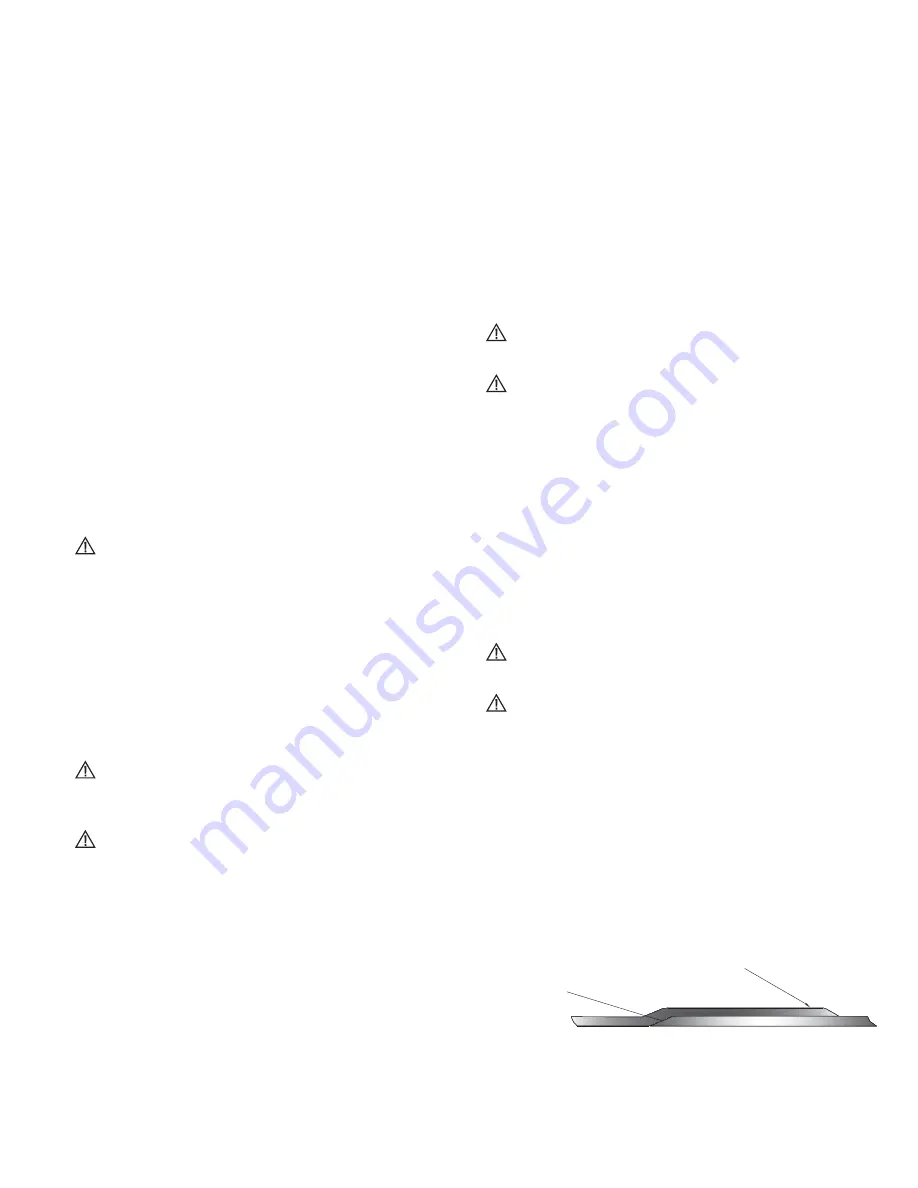
4.5.5.3 Preparation of the Gasket Tape Ends
Cut the leading and trailing ends of the gasket tape at
45 degrees per Figure 9. This initial step is required to
insure a smooth transition of the leading and trailing
ends of the tape when it is overlapped per section
4.5.5.4 (b).
Tape/Gasket-Overlap a minimum
of 0.44" (11.2 mm)
Skive ends for
smooth overlap
Figure 9
Summary of Contents for Airflex WSB11206
Page 1: ......


