25-75 kW
User's and Installation Guide
68
Note:
•
The “Permitted Maximum Power” does not mean that the UPS will be overloaded if this power value is
exceeded. For example, when selecting the 2+2 configuration, the rated UPS apparent power is 100kVA
and active power is 100kW, therefore, if load exceeds the permitted maximum power 50kW (permitted
maximum power), the UPS will not be overloaded and only the N+X (X=2) structure will be changed.
•
The “permitted maximum power”indicates the three-phase power, so the permitted maximum power of
single-phase needs to be divided by three.
Adding the UPS Module
Online
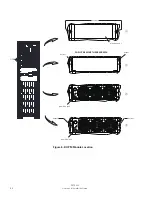
1. Choose anyone plastic cover; UPM should be installed one by one.
WARNING
The plastic panel must be installed, if the card slot is not inserted, otherwise it will cause hot air return at the rear.
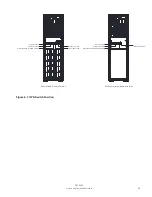
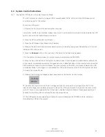
2. Remove 2pcs screw shown above and take plastic cover away. We can see the view from the front and 3
screws pre-installed, see Figure. 6-8
②
.
WARNING
Do not remove these screws
②
.
3. Set the position lock located on the front panel of the module to “ ”.
4. After UPM is installed, switch UPM lock in lock state, see Figure. 6-8
③
.
5. Right side is unlock state and the other side is lock state, see Figure. 6-8
④
.
6. Fix 2pcs screws to finish the installation and set the position lock located on the front panel of the module
to “ ” (see Figure. 6-8).
Reducing/Replacing the UPS Module Online
Removing UPM has reversed steps as adding UPM, please remove UPM from step 6 to step 1.
To replace UPM, please implement removing UPM steps and then do adding UPM steps.
WARNING
•
Before the LED is off, it is forbidden to pull out the UPM module.
•
Ensure the lock has to unlock the state, when pull out the UPM.
Summary of Contents for 93PR Series
Page 1: ...User s and Installation Guide Eaton 93PR UPS 25 75 kW...
Page 2: ......
Page 3: ...Eaton 93PR UPS 25 75 kW User s and Installation Guide...
Page 96: ......
Page 97: ......
Page 98: ...614 02087 00...


