UPS Maintenance
9-2
Eaton
®
Power Xpert
®
9395C UPS Installation and Operation Manual P-164000821—Rev 01
www.eaton.com/powerquality
l
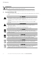
When replacing batteries, use the same number of sealed, lead-acid batteries.
l
Proper disposal of batteries is required. Refer to your local codes for disposal requirements.
l
Do not dispose of batteries in a fire. Batteries may explode when exposed to flame.
l
Do not open or mutilate batteries. Released electrolyte is harmful to the skin and eyes. It may be toxic
9.2
Performing Preventive Maintenance
The UPS system requires very little preventive maintenance. However, the system should be inspected
periodically to verify that the units are operating normally and that the batteries are in good condition.
9.2.1
DAILY Maintenance
Perform the following steps daily:
1.
Check the area surrounding the UPS system. Ensure the area is not cluttered, allowing free access to the
unit.
2.
Ensure the air intakes (vents on the front door or panels) and the exhaust openings (on top of the PM
section) are not blocked.
3.
Ensure the operating environment is within the parameters specified in paragraph 3.2.2 and Chapter 10,
“Product Specifications”.
4.
Ensure the UPS is in Normal mode (Normal status indicator is illuminated). If an alarm lamp is illuminated
or the Normal status indicator is not illuminated, contact an Eaton service representative.
9.2.2
MONTHLY Maintenance
Perform the following steps monthly:
1.
Monitor system parameters as described in paragraph Chapter 7, “Using the Color Touchscreen Control
Panel”.
2.
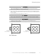
Check the UPS air filters (located behind the front panels or door) and wash or replace as necessary. See
Figure 9-1 and Figure 9-2 for filter locations, and Table 9-1 for filter sizes. Contact an Eaton service
representative for replacement filters. To remove and replace the filters:
CAUTION
Verify washed filters are thoroughly dry before reinstalling.
ATTENTION!
Vérifier que les filtres sont bien secs avant de les réinstaller.
Table 9-1. UPS Filter Sizes
Filter Location
Size
Bottom Left ISBM Section Air Filters (Continuous Static Switch)
12
” X
20”
X
0.25”
Bottom Right ISBM Section Air Filters (Continuous Static Switch)
12”
X
20”
X
0.25”
Middle Right ISBM Section Air Filter (Continuous Static Switch)
20”
X
6.3”
X
0.25”
ISBM Section Air Filters
20”
X
44”
X
0.25”
Summary of Contents for 9395C-1000/1000
Page 2: ......
Page 23: ...Section I Installation ...
Page 24: ......
Page 93: ...Section II Operation ...
Page 94: ......
Page 155: ......
Page 156: ... P 164000821 1 P 164000821 1 ...


