


11
Model 72400
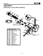
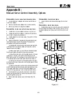
Appendix A -
Charge Pump Adapter Assembly
Disassembly -
Charge Pump Adapter Assembly
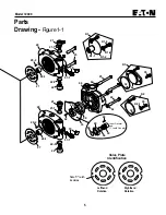
1
Remove plug, shims, spring, and poppet from adapter
assembly.
Inspection:
• Inspect the charge pump relief valve seat inside the
charge pump adapter. Check to insure that seat is smooth and
free of burrs or other defects.
• Inspect the charge pump relief valve spring.
• Inspect the bearing or bushing inside the charge pump
adapter. The bearing needles must remain in the bearing cage
and bearing at dimension shown in figure 1-2. The bushing
must have no excessive scoring.
• Inspect the gerotor pocket inside the charge pump
adapter assembly. It should not be scored excessively.
Numbered End
Gerotor Pocket
2,41 mm
[.095 in.]
Flange
Figure 1-2
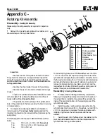
Reassembly -
Charge Pump Adapter Assembly
1
If necessary, press new bearing or bushing in adapter
assembly. The bearing to dimension shown in figure 1-2 with
the numbered end of bearing outward and closest to mounting
flange. The bushing is to be pressed flush to 0,254 mm [.010
in.] recessed.
2
Install poppet, spring, shims, new o-ring on plug, and plug
into adapter assembly. Torque plug 40,7 to 36,6 N•m [30 to 27
lbf•ft.]
Item
Qty.
Description
46-1
1
Charge Pump Adapter
46-2
1
Bearing (press fit)
46-2
1
Bushing (press fit)
46-3
1
Plug
+
46-3-1
1
O-ring
46-4
ƒ
Shims
46-5
1
Spring
46-6
1
Poppet
ƒ
Shim as required
46-2
46-3
46-3-1
46-4
46-5
46-6
46-1
Gerotor Ring
Pocket
Charge Pump
Suction Port
Bushing
Bearing


