Eaton 5P 1500 RL Installation And User Manual Download Page 4

Page 4

Safety of Persons

The system has its own power source (the battery). Consequently, the power outlets may be energized
even if the systems is disconnected from the AC power source.

Dangerous voltage levels are present within the system. It should be opened exclusively by qualified
service personnel.

The system must be properly grounded.

The battery supplied with the system contains small amounts of toxic materials.
To avoid accidents, the directives listed below must be observed:
- servicing of batteries should be performed or supervised by personnel knowledgeable about betteries
and the required precautions.
- when replacing batteries, replace with the same type of battery module.
- do not dispose of the battery module in a fire.  The battery module may explode.
- the battery module constitutes a danger (electrical shock, burns). The short-circuit current may be very
high.

Precautions must be taken for all handling: 

Wear rubber gloves and boots.

Do not lay tools or metal parts on top of the battery module.

Disconnect charging source prior to connecting or disconnecting battery terminals.

Determine if battery is inadvertently grounded.  If inadvertently grounded, remove source from ground.
Contact with any part of a grounded battery can result in electrical shock. The likelihood of such shock
can be reduced if such grounds are removed during installation and maintenance (applicable to
equipment not having a grounded supply circuit).

Product Safety

The UPS connection instructions and operation described in the manual must be followed in
the indicated order.

A protection circuit breaker must be installed upstream and be easily accessible.
The system can be disconnected from the AC power source by opening this circuit breaker.

Check that the indications on the rating plate correspond to your AC powered system and to
the actual electrical consumption of all the equipment to be connected to the system.

For PLUGGABLE EQUIPMENT, the socket-outlet shall be installed near the equipment and shall
be easily accessible.

Never install the system near liquids or in an excessively damp environment.

Never let a foreign body penetrate inside the system.

Never block the ventilation grates of the system.

Never expose the system to direct sunlight or source of heat.

If the system must be stored prior to installation, storage must be in a dry place.

The admissible storage temperature and humidity range:

1 Month: 

113 to 122°F / 45 to 50ºC

3 Month: 77 to 113°F / 25 to 45ºC
1 Year: 14 to 77°F / -10 to 25ºC
Humidity: 0 to 85% RH

The system is not for use in a computer room AS DEFINED IN the standard for the Protection
of Information Technology Equipment, ANSI/NFPA 75 (US installations only).

 Contact Eaton resellers to order a special battery kit, if needed to meet the ANSI/NFPA 75 requirement.

Special Precautions

All handling operations will require at least two people (unpacking, installation in rack system).

Before and after the installation, if the UPS remains de-energized for a long period, the UPS must be
energized for a period of 24 hours, at least once every 3 months (recommended storage temperature
is 77°F (25 °C)). This charges the battery, thus avoiding possible irreversible damage.

During the replacement of the battery module, it is imperative to use the same type and number of
elements as the original battery module provided with the UPS to maintain an identical level of
performance and safety. In case of doubt, don’t hesitate to contact your Eaton representative.

Summary of Contents for 5P 1500 RL

Page 1: ...1U Rack Model 5P 1500 RL Copyright 2018 Eaton All rights reserved Installation and User Manual ...

Page 2: ...Page 2 ...

Page 3: ...f waste sent for incineration or land fills and minimize any potential negative impact on human health and environment Li ion Supplier s Declaration of Conformity 47 CFR 2 1077 Compliance Information Unique Identifier EATON 5P1500R L Responsible Party U S Contact information Applicant Eaton Corporation Address 8609 Six Forks Road Raleigh NC 27615 USA Phone Number 800 356 5794 FCC Compliance Statem...

Page 4: ...ly accessible The system can be disconnected from the AC power source by opening this circuit breaker Check that the indications on the rating plate correspond to your AC powered system and to the actual electrical consumption of all the equipment to be connected to the system For PLUGGABLE EQUIPMENT the socket outlet shall be installed near the equipment and shall be easily accessible Never insta...

Page 5: ... Unpacking and Contents Check 12 3 2 Rack Installation 12 3 3 Wall Mount Installation 13 3 4 Communication Ports 14 4 Operation 15 4 1 Start up and Normal Operation 15 4 2 Starting the UPS on Battery 15 4 3 UPS Shutdown 15 4 4 Operation on Battery Power 15 4 5 Return of AC Input Power 16 4 6 UPS Remote Control Functions 16 5 Maintenance 17 5 1 Troubleshooting 17 5 2 Battery Module Replacement 18 6...

Page 6: ...recyclable and bear the appropriate identi cation symbol 01 PET Materials Abbreviations Number in the symbols 1 0 T E P t a l a h t h p e r e t e n e l y h t e y l o P 2 0 E P D H e n e l y h t e y l o p y t i s n e d h g i H 3 0 C V P e d i r o l h c l y n i v y l o P 4 0 E P D L e n e l y h t e y l o p y t i s n e d w o L 5 0 P P e n e l y p o r p y l o P 6 0 S P e n e r y t s y l o P Follow all...

Page 7: ... Communication Port Ground Screw RS232 Communication Port Connector for ROO or RPO Control Slot for Optional Communication Card Outlets for connection of critical equipment Primary group Group 1 programmable outlets for connection of equipment Group 2 programmable outlets for connection of equipment Attached 6 ft input power cord for AC power source LED indicating site wiring fault SWF alarm ...

Page 8: ... On Battery Indicator yellow Power On Indicator green On Off Button Down Enter Escape The following table shows the indicator status and description Green On Normal mode Yellow On Battery mode Red Active alarm see Troubleshooting on page 19 Normal mode 100 10min 100 720 W 800VA Efficiency 98 Up ...

Page 9: ...d Normal mode The UPS is operating normally The UPS is powering and protecting the equipment In AVR mode No beep The UPS is operating normally but the utility voltage is outside normal mode thresholds The UPS is powering connected equipment through the internal Automatic Voltage Regulation AVR device The equipment is still normally protected On Battery Battery LED is on 1 beep every 10 seconds A u...

Page 10: ... t n e d I Com card address 2 6 User Settings The following table displays the options that can be changed by the user s g n i t t e S t l u a f e D s g n i t t e S e l b a l i a v A n o i t p i r c s e D Local Settings Language English Français Deutsch Italiano Português Español Русский Menus status notices and alarms UPS fault Event Log data and settings are in all supported languages English Us...

Page 11: ...t 10 seconds prior to restart if disabled shutdown sequence will not complete and restart will occur immediately Enable Auto restart Disable Enable Enables the product to restart automatically when mains recovers after a complete battery discharge Enable Energy saving Disable Enable If enabled UPS will shutdown after 5 min of back up time if no load is detected on the output Disable Sleep mode Dis...

Page 12: ...te Recycling symbols are printed on the packing materials to facilitate sorting Front Panel Parts 5P UPS 1U Rack Kit Quick Start Safety Instructions RS232 Communication Cable USB Communication Cable 3 2 Rack Installation Follow Steps 1 through 4 for mounting the UPS on the rails 1 1 2 2 3 3 4 4 The rails and necessary hardware are supplied by Eaton ...

Page 13: ...Page 13 3 Installation 3 3 Wall Mount Installation Follow Steps 1 and 2 for mounting the UPS on the wall Allow room for connected cables 2 2 2 1 1 1 ...

Page 14: ...of the communication cards optional 3 It is not necessary to shutdown the UPS before installing a communication card 1 Remove the slot cover 3 secured by screws 2 Insert the communication card in the slot 3 Secure the card cover with the 2 screws Characteristics of the optocouplers communication port optional Pins 1 3 4 5 6 10 not used Pin 2 common user Pin 7 low battery Pin 8 operation on battery...

Page 15: ...N OFF Settings on page 12 To start the UPS on battery 1 Press the button on the UPS front panel until the display illuminates and shows UPS starting The UPS cycles through Standby mode to Battery mode The indicator illuminates solid and the UPS powers your equipment 2 Check the UPS front panel display for active alarms or notices other than the Battery mode notice and notices that indicate missing...

Page 16: ... a normally closed volt free contact 60 Vdc 30 Vac max 20 mA max 0 75 mm2 18 AWG cable cross section between the two pins of connector 4 see diagram 4 Contact open UPS shutdown Contact closed UPS start up UPS connected to AC power and AC power is available Note The local ON OFF control using the button overrides the remote control function 4 Contact open UPS shutdown indicator illuminates To retur...

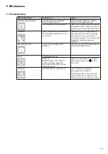
Page 17: ...some of the equipment from the UPS The UPS continues to operate but may shutdown if the load increases The alarm resets when the condition becomes inactive End of battery life The end of the battery life is reached Contact your service representative for battery replacement Event A UPS event occurs Example Remote Power OFF the RPO contact has been activated to shutdown the UPS and now prevents res...

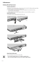
Page 18: ...her metal objects from the hands and arms use tools with an insulated handle Refer to page 4 for more safety precautions before servicing the battery components Battery Module Removal This operation must be performed when the UPS is OFF Battery Module Replacement Carry out the above instructions in reverse order To ensure safety and high performance use only batteries supplied by Eaton Take care t...

Page 19: ... temperature range 41 to 104 F 5 to 40 C Storage temperature range 14 to 122 F 10 to 50 Relative humidity 0 to 85 without condensation Noise level 40 dBA 1 The high and low thresholds can be adjusted using UPS settings 2 Down to 40 Hz in low sensitivity mode programmable using UPS settings 3 Adjustable to 100 120 125V must be set to the identical AC power source value This product is designed for ...

Page 20: ...614 40000 00 ...

Reviews: