18
5.6 CHG CNTL board
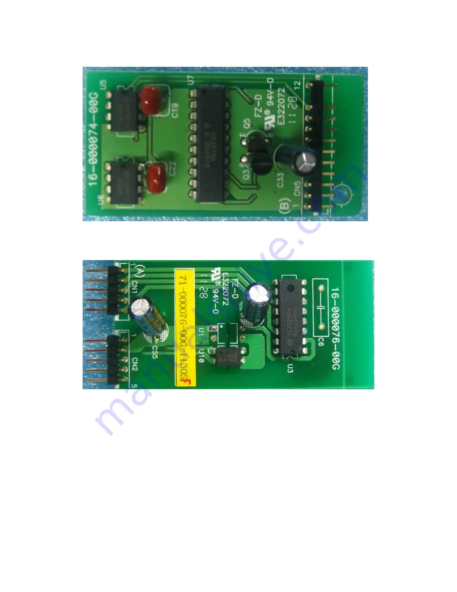
It provides PWM waves to control the charging MOSFET when the battery is in charging
mode.
5.7 DISCHG CNTL board
It provides PWM waves to control the charging MOSFET when the battery is in
discharging mode.
Page 1: ...1 SOLAR POWER SYSTEM SERVICE MANUAL IGrid SS 3KW Plus...
Page 2: ...y 11 4 2 Boost circuit 12 4 3 Inverter 12 4 4 Charger Discharger 13 4 5 EMI Board 13 5 Function explanations for each PCB 15 5 1 MAIN board 15 5 2 CNTL board 16 5 3 BAT board 16 5 4 COM board 17 5 5 P...
Page 3: ...s section explains you all the PCBs of the Inverter system Interface this section shows you the LCD interface Trouble Shooting this section gives you the way to find the problems Test Step this sectio...
Page 4: ...t source voltage and frequency is within the maximum range before service Don t remove the battery or switch off the breaker of battery when the inverter is running otherwise the inverter may change t...
Page 5: ...input data Max DC Power 3200W Nominal DC voltage 360Vdc Max Input voltage Maximum PV open voltage 500Vdc System start up voltage 116V 10V whether PV establish control power Initial feeding voltage 15...
Page 6: ...8 220 240 Vac Nominal output frequency 50 Hz 0 1Hz O P voltage distortion 3 for linear load 5 for non linear load O P DC component 50mV Transient O P voltage range 230 10 Transient Time 120ms Maximum...
Page 7: ...stages First max current until 57V then 57V during until charging current down to 5 Amp then go to float at 55V Absorption charger voltage 57 0 Vdc Floating charger voltage 55 0 Vdc Battery overcharge...
Page 8: ...8 IUoU charging process...
Page 9: ...provides EMI filter function The input and output EMI filters can prevent the PV Inverter from being interference by external electronic magnetic noise which is generated by other electronic system a...
Page 10: ...when the efficient power from PV modules or the utility power is generated more than the load needed On the contrary the block will discharge the battery power to the DC BUS The switch block is contr...
Page 11: ...voltage about 150Vdc ACSPS The input source of the main SPS can be any of the DC BUS voltage the output of the battery SPS or the output of the grid SPS Because the PV input can power to the DC BUS th...
Page 12: ...as HCT The 12V_RLY is supplied to fans and relays 4 2 Boost circuit Figure 4 4 Boost circuit As shown in the Figure 4 4 when Q1 is on the current will increase to store energy in choke L2 and capacit...
Page 13: ...on and off in this mode The control board will disable the charge control circuit and enable the discharge control circuit when the battery is working in discharging mode In this mode the discharge co...
Page 14: ...14 EMI board is connected between the output of inverter and output terminal SWITCH block Figure 4 8 Topology of the EMI...
Page 15: ...07 XXG 1 Note XX in the serial number is the version of the PCB It may be modified according to releasing version in the future 5 1 MAIN board Figure 5 1 picture of MAIN board The MAIN board consists...
Page 16: ...r is the DPS Its main function is to control power and safety independence The slave controller is the MCU Its main function is to control the safety with DSP LCD display and communication 5 3 BAT boa...
Page 17: ...17 5 4 COM board The COM board provides RS232 and USB interface to the users 5 5 PANEL board The PANEL board is used to provide LCD interface...
Page 18: ...TL board It provides PWM waves to control the charging MOSFET when the battery is in charging mode 5 7 DISCHG CNTL board It provides PWM waves to control the charging MOSFET when the battery is in dis...
Page 19: ...board The Switch Power Supply SPS supplies DC power for Inverter operation including 5V 12V 12V and 15V The input source of the SPS is from BUS voltage the output of the battery SPS or the output of t...
Page 20: ...quency Vac voltage Hz frequency Indicates AC output power voltage frequency or Load percentage KW power Vac Voltage Hz frequency Load percentage Indicates PV input voltage or power Volt voltage KW pow...
Page 21: ...21 Indicates solar panels Indicates grid Indicates battery Indicates load Indicates energy generated...
Page 22: ...n Flashing Means Possible cause Action PV module disconnect PV voltage is lower than 100V 1 Waiting for sunlight to generate sufficient power 2 Check if PV cables are connected correctly and firmly Li...
Page 23: ...ess check the temperature sensor and the related circuit 09 PV high voltage 1 Check if the open PV voltage is greater than or close to 500VDC 2 If PV voltage is less than 500VDC and the problem still...
Page 24: ...he components listed in section 7 2 4 to find out which block fails 7 2 1 Basic Instruments and tools 1 One computer with RS232 port and one standard RS232 cable 2 Wire cutters and clamps 3 One electr...
Page 25: ...SFET D S short or open D1 D7 D6 D3 D2 D8 D9 D20 Power Diode Short or open U4 Optocoupler Input and output short or open U3 Control IC Power Pin and o p pin short R7 R11 Resistance Short or open AC EMI...
Page 26: ...d it means that the Optocoupler may also be damaged extremely So replace it at the same time 7 2 2 2 Major parameters of Inverter section The most likely problems occur on the INV section including br...
Page 27: ...100 Infinite or value change D1 D7 D6 D3 D2 D20 Diode Voltage Droop 0 45V Short or open U3 Power Pin Pin7 Pin5 Resistance 230K Vcc short to GND o p Pin Pin6 Pin5 Resistance 47k Short or open U4 Pin1...
Page 28: ...istance 4 7k Short or open R39 R40 R41 R42 R49 R50 R52 R53 R101 R102 Resistance 10 Short or open D14 D15 D17 D18 need be removed from PCB Diode Voltage Droop 0 6V Short or open D13 D19 Diode Voltage D...
Page 29: ...re is no other mistake repair grid SPS again and restart test step from step 1 6 Disconnect the utility connect the battery and press the ON button for a short time less than 1s The LCD will light up...