


6
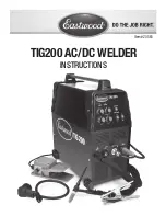
COMPONENTS AND CONTROLS
1. Power Switch
– The Power Switch also serves as the overload Circuit Breaker and is located at
the right of the rear panel
(FIG. C)
.
2. Amperage (Front Panel)
– Set the Output Amperage Knob marked “A”
(FIG. A)
, located at up-
per left of the top panel, to an appropriate setting based on the thickness and type of the metal
being welded. (Refer to Data Chart for actual settings.)
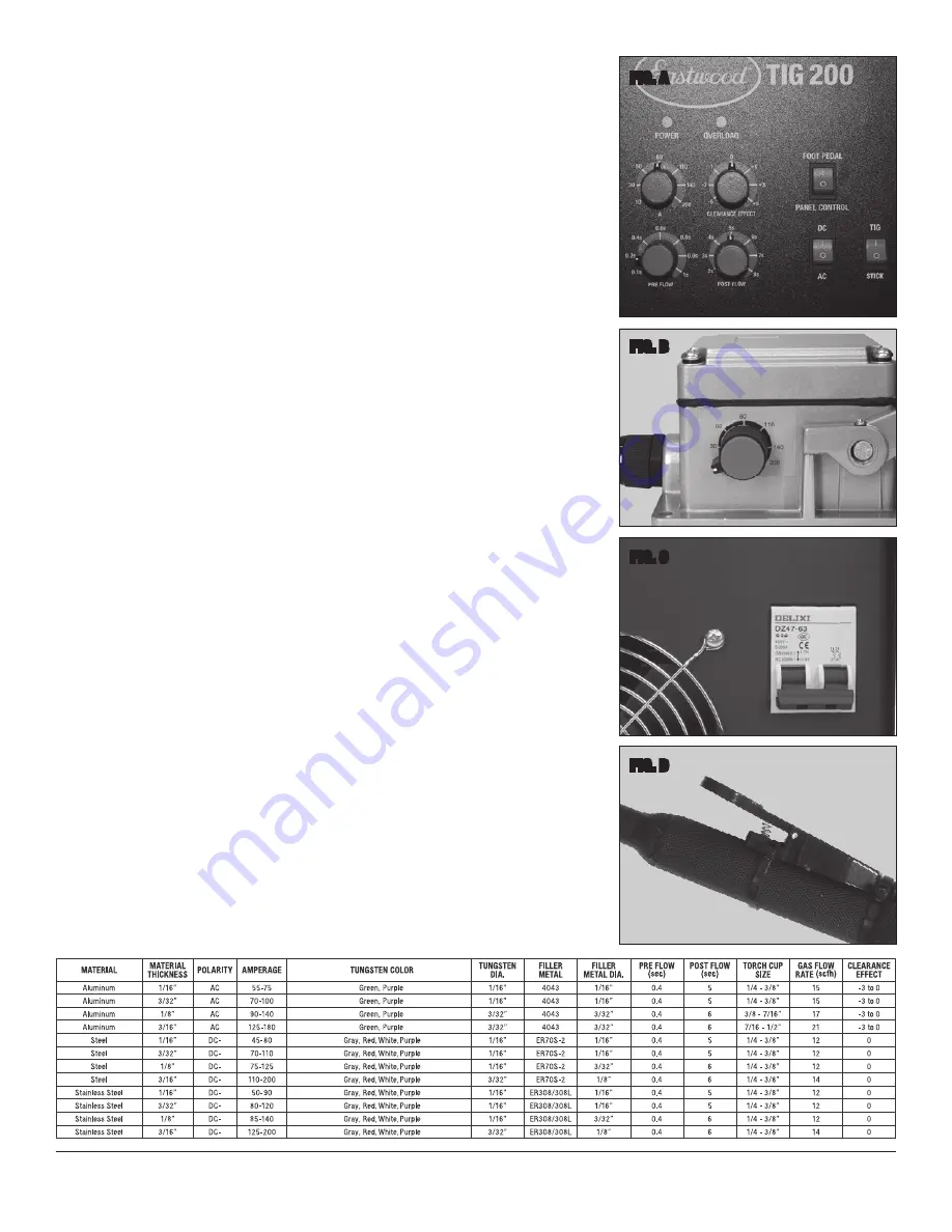
3. Amperage (Foot Pedal)
– Same operation as the panel control but is used while the foot pedal
is in use
(FIG. B)
.
4. Clearance Effect
– The Clearance Effect Knob
(FIG. A)
is located at the upper right of the top
panel. Clearance Effect will control how much cleaning versus penetration occurs. The more
negative the value will result in greater penetration and less cleaning and the more positive the
value will result in less penetration but greater cleaning.
5. Pre Flow
– The Pre Flow Knob located at the lower left of the top panel
(FIG. A)
controls the
time (in seconds) that the shielding gas starts to fl ow after the trigger or foot pedal is pressed
before the arc starts. (Refer to Data Chart for actual settings.)
6. Post Flow
– The Post Flow Knob located at the lower right of the top panel
(FIG. A)
controls
the time (in seconds) that the shielding gas continues to fl ow after the trigger or foot pedal is
released. (Refer to Data Chart for actual settings.)
7. Gas Flow
– The included regulator limits the shielding gas fl ow from the bottle and also displays
how much gas is left in the bottle. The Gas Flow Indicator Gauge is located on the left side
and is generally set between 12 to 21 SCFH. (Refer to Data Chart for actual settings.) This is
explained in further detail in the Preparing to Weld section of this manual. The gauge on the right
indicates the pressure left in the tank.
8. AC/DC
– The DC setting is used for welding steel and stainless steel while the
AC setting is used for welding aluminum
(FIG. A)
. (Refer to Data Chart for actual settings.)
9. TIG/Stick Switch
– The TIG/Stick Switch allows selection between TIG Welding or Stick Weld-
ing confi guration.
NOTE:
Stick Weld Torch is
Not Included
.
10. Foot Pedal/Panel Control
– The Foot Pedal/Panel Control selection switch is located at the
upper right of the top panel and when set in the ‘Foot Pedal’ position, the Foot Pedal control is
activated. When set to the ‘Panel Control’ position, the Torch Trigger is activated
(FIG. A)
.
11. Torch Switch
– The switch on the torch (Fig. D) controls starting and stopping the arc. When
using the torch switch the Amperage is set on the adjustment knob on the front panel of the
welder.
12. Foot Pedal
– The foot pedal is for starting and stopping the arc as well as controlling the Am-
perage during the weld. When using the foot pedal the Amperage is set by the adjustment knob
on the side of the foot pedal
(FIG. B)
.
FIG. A
FIG. B
FIG. C
FIG. D
DATA CHART
(ALSO LOCATED ON TOP OF WELDER)


