


8
Eastwood Technical Assistance: 800.343.9353 >> [email protected]
INSTALLING WIRE SPOOL
The Eastwood MIG135 can be used with either a 4" or an 8" Wire Spool. To use the larger 8" spool an included adaptor is necessary.
To install a 4" Wire Spool:
1.
Open the door of the welder and remove the wing nut
(FIG. F2)
, spacer
(FIG. F1)
, and 8" Spool Adaptor
(FIG. F3)
from the Wire Spool Spindle.
2.
Slide the 4" Wire Spool onto the spindle and reinstall the spacer and the wing nut and place the 8" Spool
Adaptor in a safe place if it is needed in the future.
3.
To set the tension on the wire, tighten the wing nut till there is a slight resistance to spinning the wire spool
on the spindle. If the tension is set too loose the wire spool will spin on the shaft and unspool all of the wire.
If the tension is too tight, the drive roller will have issues pulling the wire off the spool and some slipping
may occur.
NOTE:
Hold exposed wire end to keep the spool from unraveling.
To install an 8” Wire Spool:
1.
Open the door of the welder and remove the wing nut, spacer, and 8" Spool Adaptor from the Wire Spool Spindle.
2.
Slide the 8" Wire Spool Adaptor into the center of the wire spool.
3.
Slide the 8" Wire Spool Adaptor with the wire spool installed onto the spindle and reinstall the spacer and
the wing nut.
4.
To set the tension on the wire, tighten the wing nut till there is a slight resistance to spinning the wire spool on the spindle. If the tension is set too loose
the wire spool will spin on the shaft and unspool all of the wire. If the tension is too tight, the drive roller will have issues pulling the wire off the spool and
some slipping may occur.
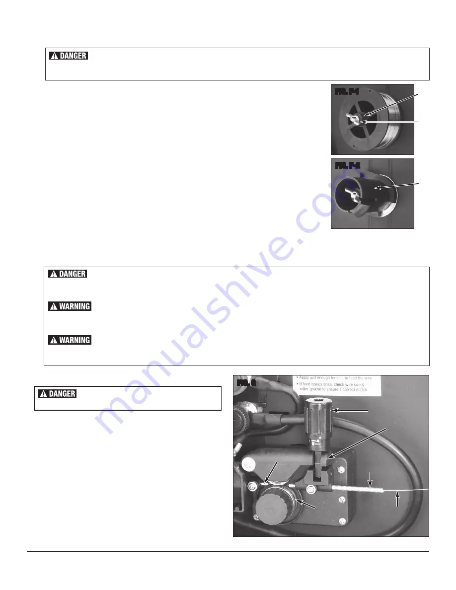
THREADING WELDING WIRE THROUGH THE DRIVE TO THE WELDING GUN
1.
Unlock the Pressure Adjuster
(FIG. G1)
and lift up the rocker arm
(FIG. G2)
. Ensure that the wire drive roller is appropriate to the welding
wire size, see following page describing the installation of the Drive Roller.
The Drive Roller comes installed for 0.6mm/0.023" wire.
2.
Pull out the welding wire
(FIG. G3)
from the wire spool carefully;
NOTE:
Do not let go of the wire prior to step 5 or the spool will
unravel and be useless.
3.
Cut off the small piece of the curved segment at the front of welding
wire and straighten the welding wire approximately 3.0" long.
4.
Thread the welding wire through the Guide Pipe
(FIG. G4)
and over
the wire Drive Roller
(FIG. G5)
and into the torch hole
(FIG. G6)
.
5.
Reattach the Rocker Arm
(FIG. G2)
and reset the Pressure Adjuster
(FIG. G1)
.
FIG. G
✓
G2
✓
G1
✓
G3
✓
G4
G5
G6
FIG. F-2
✓
F3
✓
F2
✓
F1
FIG. F-1
ELECTRIC SHOCK HAZARD!
The electrode and work (or ground) circuits are electrically “hot” when the welder is on. Do not touch these “hot” parts with your
bare skin or wet clothing.
ELECTRIC SHOCK HAZARD!
The electrode and work (or ground) circuits are electrically “hot” when the welder is on. Do not touch these “hot” parts with your bare skin
or wet clothing.
WELDING WIRE CAN BE DANGEROUS!
• Never point the welding gun at any part of the body, other people, or metal surfaces.
• Wear safety glasses and handle welding wire safety as it can be sharp and cause injury.
MOVING PARTS CAN BE DANGEROUS!
• Use care when working near the drive motor assembly as it can pinch.
• Do not put fingers or other body parts between moving parts.
ELECTRIC SHOCK CAN CAUSE INJURY OR DEATH!
Disconnect welder from power supply before beginning.
✓
✓


