To order parts and supplies: 800.343.9353 >> eastwood.com
15
MAINTENANCE
PINCH AND CRUSH HAZARD!
Keep fingers and hands away from moving parts when operating.
INJURY HAZARD!
This tool can quickly start up while connected to an electrical supply causing serious personal injury. Always disconnect the
Tire Machine from the electrical supply before making adjustments or performing maintenance.
EYE INJURY HAZARD!
Moving/rubbing components under great pressures can suddenly eject particles at high velocity. Always wear ANSI approved
eye protection when operating this equipment.
BURST HAZARD!
Excessive air pressure can cause tool to explode resulting in tool damage and personal injury. Do not exceed 145 psi [10 bar] of
tool inlet air pressure.
BURST HAZARD!
Disconnect compressed air source and electrical supply before servicing Tire Machine.
ADJUSTMENTS
The Mount/Dismount Shoe positioning was adjusted at the factory
so that the inner curve will be concentric to the outer edge of wheel
rims with the
“Duckhead”
and
“Ducktail”
sections at equal dis-
tance from any size wheel rim diameter. With use, this may require
periodic checking and adjustment. To do so:
• Place a wheel face-up on the Turntable
“jj”
.
• Depress the Rim Clamp Pedal
“mm”
to clamp it in place
(FIG 6)
.
• Release the Lock Lever to unlock the Slide Shaft
“bb”
.
• Allow the Mount/Dismount Shoe
“Ducktail”
Plastic Glide
[G]
to stop just above the face of the rim then lock the
Slide Shaft.
• Rotate the Wheel Diameter Adjustment Knob
“nn”
inward
or outward to determine the distance of the “Duckhead”
Replaceable Plastic Glide
[H]
of the Mount/Dismount
Shoe in relation to the edge of the wheel rim bead area
(FIGS 9 & 10)
.
• Check for any variation in distance from the
“Duckhead”
and the
“Ducktail”
ends of the Mount/Dismount Shoe and
the outer edge of the wheel rim.
• If the distances are unequal, adjustment is required.
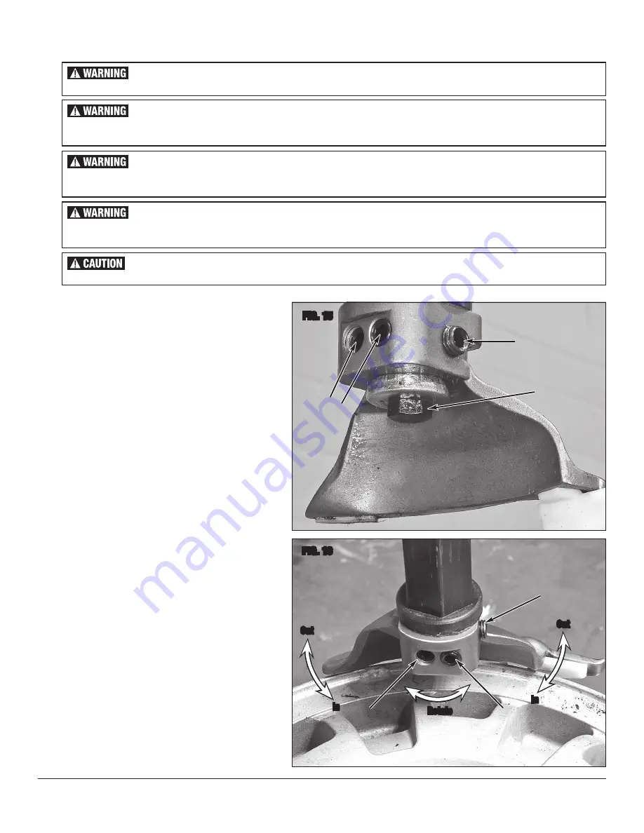
To adjust:
- Loosen the large bolt at the underside of the Mount/
Dismount Shoe with a 16mm wrench (not included)
(FIG 15)
.
- Loosen the set-screw on the
“Duckhead”
side with a
6mm hex key (not included)
(FIG 15)
.
- Using the same 6mm hex key, turn the 2 adjusting
screws on the inner side in or out to rotate the Mount/
Dismount Shoe as required to bring it into alignment
(FIG 16)
.
- Re-tighten the set-screw and the large bolt to lock in
the adjustment and check once again.
FIG. 15
FIG. 16
✓
Loosen
✓
Loosen
Adjust
In/Out
✓
✓
✓
Loosen
✓
✓
Adjust
In/Out
Adjust
In/Out
Rotate
Out
Out
In
In


