background image

To order parts and supplies: 800.343.9353  >>  eastwood.com 

9

INSTALLING  

REMAINING COMPONENTS
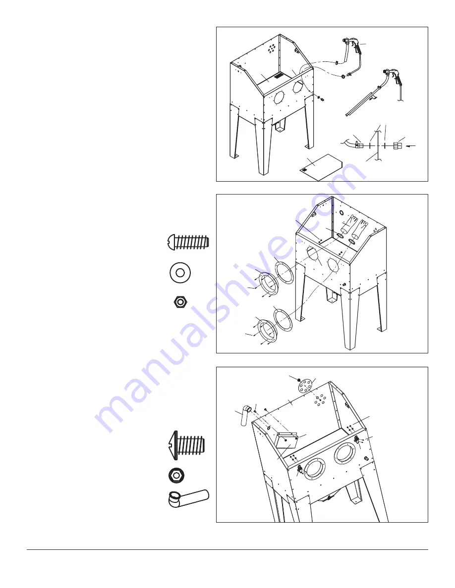
1. 

Stand assembled unit up on it’s legs 

(FIG. 15)

.

2. 

Tighten leg screws to ensure unit sits level.

3. 

Install the Media Blasting Gun (W) Suction Hose to the Media  
Suction Tube (O), secure with a Hose Clamp and tighten 

(FIG. 15)

.

4. 

Place the Media Blasting Gun (W) Air Supply Hose Fitting through 
the through hole in the lower right corner of the Cabinet Front 
Panel (H) using a large flat washer on either side. Wrap thread 
sealing tape around fitting threads and secure with the  
Air Supply Fitting Nut 

(FIG. 15)

.

5. 

Let the Media Blasting Gun (W) hang out of the right front corner 
of the Cabinet 

(FIG. 15)

.

6. 

Set the Shelf (B) (with angled cut off corner toward right front of 
cabinet) and allow it to rest on the hopper flanges and Shelf  
Floor Support (Q) 

(FIG. 15)

.

7. 

From the outside, install 2 sets of Seal Rings (U) and Glove Seats 
(V) into the large holes in the Cabinet Front Panel (H) and secure 
with twelve M4 x 16mm screws (BB), flat washers, (GG) and nuts 
(FF) 

(FIG. 16)

.

8. 

Fit 2 Hose Clamps (S) over the Glove Sleeves then slide the Gloves 
(R) fully over the Glove Seats (V) then tighten Hose Clamps (S) 
securely 

(FIG. 16)

NOTE:

 Be sure to install left and right hand 

gloves on the correct side and position them with thumbs upward.

9. 

From the outside, install the Air Input Regulating Disk (LL) over the 
six hole array on the upper rear corner of the Cabinet Back Panel 
(C) and secure with Knob Screw (MM) 

(FIG. 17)

.

10. 

From the inside, install the Vacuum Elbow (SS) with grommet. 
Next, install the Vacuum Baffle (X) over the vacuum hole on the 
upper left corner of the Cabinet Back Panel (C) and secure with  
four M6 x 12mm screws (AA) and nuts (EE) 

(FIG. 17)

.

FIG. 15

FIG. 16

FIG. 17

H

B

W

Air Supply 

Hose Fitting

Washer

Air Supply 

Fitting Nut

Air Flow

H

H

S

R

U

V

BB

V

U

BB

FF, GG

AA

C

MM

LL

FF, GG

CC

EE

X

M

M

H

12 Pcs.  BB  M4 x 16mm Screw

12 Pcs.  GG  M4 Washers

12 Pcs.  FF  M4 x 12mm Screw

B

4 Pcs.  AA  M6 x 12mm Screw

4 Pcs.  EE  M6 Nut

1 Pc.  SS  Vacuum Elbow

SS

Summary of Contents for 20557

Page 1: ...ABRASIVE MEDIA BLAST CABINET B60 INSTRUCTIONS Item 20557...

Page 2: ...ure to crystalline silica may cause silicosis a serious lung disease cancer and death Dust generated by the blasting process can contain hazardous materials such as lead zinc chromate cadmium and othe...

Page 3: ...l Ring 2 V Glove Seat 2 W Media Blasting Gun 1 X Vacuum Baffle 1 Y Hopper Bottom Frame 1 Z Hopper Drain Latch 1 Part Description Qty AA M6 x 12mm Screw 118 BB M4 x 16mm Screw 15 CC M4 x 10mm Screw 30...

Page 4: ...g Foam between panels Do not fully tighten screws at this time FIG 2 4 Attach 2nd Hopper Side Panel L to opposite side of Hopper Front Panel K with five M6 x 12mm screws AA and nuts EE trapping the Se...

Page 5: ...er Assembly with eight M4 x 10mm screws CC and 4mm Flat Washers GG Tighten screws FIG 5 5 Install the Hopper Drain Door N to Hopper Back Panel J with three M6 x 12 mm screws and tighten FIG 5 6 Attach...

Page 6: ...two M6 x 12mm screws AA and nuts EE FIG 7 2 Peel away protective paper and apply Thin Sealing Foam KK on the upper OUTER surface of the Hopper Side Panels L Wrap the Sealing Foam around the front and...

Page 7: ...ard FIG 9 2 Install Shelf Floor Support Q NOTE open side downward to Cabinet Left Side Panel E with one M6 x 12mm Screws AA FIG 9 3 Attach Cabinet Right Side Panel I Shelf Floor Support Q with five M6...

Page 8: ...his time FIG 12 3 Peel away protective paper and apply Thin Sealing Foam KK along the front facing flanges of Cabinet Side Panels E and I and Hopper Front Panel K FIG 13 4 Attach Cabinet Front Panel H...

Page 9: ...Seats V into the large holes in the Cabinet Front Panel H and secure with twelve M4 x 16mm screws BB flat washers GG and nuts FF FIG 16 8 Fit 2 Hose Clamps S over the Glove Sleeves then slide the Glo...

Page 10: ...tach Blue Wire to Blue wire connection and Brown Wire to the Gray wire connection FIG 19 NOTE Needle Nose pliers may be useful for inserting wires to switch connection 17 Attach Switch F to Cabinet S...

Page 11: ...re to 90 PSI maximum 80 PSI is ideal Excessive air pressure can cause permanent damage to the unit For best results a heavy duty type vacuum with 1 0 to 2 0 peak horsepower is recommended Slip the hos...

Page 12: ...tlet and momentarily depress trigger Media is Contaminated Drain and sift blast media to remove debris before re use View in Cabinet Becomes Obstructed Vacuum May Not be Operating Correctly If dust cl...

Reviews: