background image

23

TROUBLESHOOTING AND REPAIR

assembly before attempting to start unit. Do not
attempt to start unit if extra hardware is left over
after reassembly is complete. Check all hammer
assemblies before proceeding.

Chipping Knives

Chipping knives should be resharpened or replaced
when tree limbs and branches require extra force to feed
completely into the chipper block.

Chipping knives may be resharpened until the distance
between the mounting holes and the top corner of the
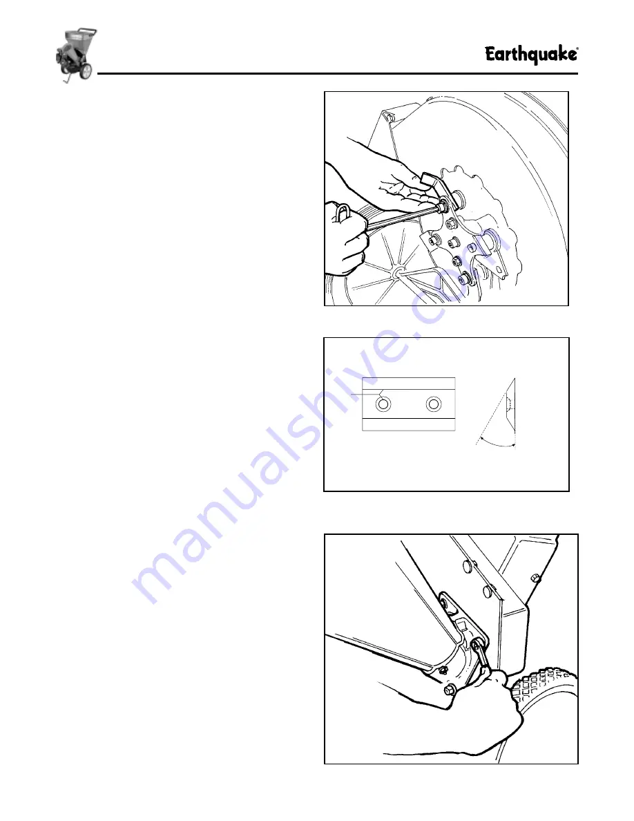
blade bevel is 1/16” apart.  (See Figure 16.)

To inspect and service the cutting knives, follow these
steps:

1. Turn engine off, allow rotor to stop completely,

and disconnect spark plug wire.

2. See Figure 10. Detach the shredder hopper from the

rotor housing leaving the liner and handle in place on
the hopper.

3. See Figure 17. Using an 1/2” box wrench or socket

remove the chipper cone to expose the oval chipping
block and one chipping knife.

4. Using a 1/4” hex wrench, loosen and remove the two

socket head cap screws holding the chipper knife in
place (access the screw heads from the rear of the
unit), and remove the chipper knife. See Figure 18 for
location and temporary removal of an access plug
that permits removal of the capscrews.

5. See Figure 19. Remove both knives through the

opening in the front of the chipper/shredder, and
sharpen equally or replace both blades to ensure
proper balancing and correct chipping action.

NOTE: Slow-speed water-cooled grinding is
suggested to help maintain blade temper and a long-
lasting sharp edge. Rapid grinding and heating of
blades will soften the edges, making repeated
sharpening necessary.

Chipper knives require a 30° bevel on the cutting
edge (see Figure 16) for efficient chipping action.

Contact your local dealer or blade sharpening
service if you prefer not to sharpen the blades
yourself.

6. Clean the chipper knife mounting areas before

reinstalling the blades to ensure a flat mounting
surface.

Figure 15. Reassembling Shredder Hammer

30

°

Top View

Side View

Figure 16. Chipper Knives Minimum Cutting Edge

Figure 17. Removing Chipper Cone to Expose
Chipping Knives

Summary of Contents for Beaver

Page 1: ...onal injury to you and or bystanders and risk of equipment and property damage The triangle in the text signifies important cautions or warnings which must be followed Engine exhaust from this product...

Page 2: ...rect any defect caused by faulty material or workmanship All repairs made under warranty must have prior approval from Ardisam Inc Items subject to normal wear and tear such as belts batteries tines s...

Page 3: ...g contact your local dealer for an exact replacement Assemble the unit in the sequence indicated in the assembly instructions Make sure all hardware is properly tightened after assembly is completed a...

Page 4: ...redder in an area where sparks from the muffler could ignite surrounding brush or flammable materials See following Fire HazardWarning SPARK FIRE HAZARD GAS ENGINES MAY REQUIRE A SPARK ARRESTER FOR SA...

Page 5: ...lid material that may be preventing the unit from operating properly Check for loose parts and loose or missing hardware and repair or replace as required Check the oil level in the engine crankcase S...

Page 6: ...ined for transportation Always observe safe refueling and fuel handling practices when refueling the unit after transportation or storage Always follow the engine manual instructions for storage prepa...

Page 7: ...cket 1 4 20 x 3 4 6 NUT Flange Whiz lock 1 4 20 6 WASHER 1 4 4 Be sure to clean all hardware threads of paint and debris before assembling CHIPPER CONE 1 See Figure 1 Position the chipper cone assembl...

Page 8: ...of the metal hopper liner Do not tighten at this time 4 Make sure the hopper is properly seated on the rotor housing and then tighten all hardware securely DISCHARGE BAG Your unit comes equipped with...

Page 9: ...ft materials to be ejected freely from the machine C Bag The two bushel bag is standard equipment and attaches in seconds for direct one step bagging D The Support Leg and Wheels The sturdy support le...

Page 10: ...2 3 s e v i n K g n i p p i h C 2 2 s r e m m a H g n i d d e r h S r a l u g n a i r T 2 s r e m m a H J 2 r a l u g n a i r T 2 s r e m m a H J 2 y t i c a p a C r e d d e r h S g n o L 8 1 x 2 1 g...

Page 11: ...is created which pulls waste down into the shredder hopper and into the grinding chamber These spinning fan blades also create a blowing force that ejects the shredded or chipped material out of the d...

Page 12: ...y and allow to return normally 6 When engine starts gradually move choke lever to no choke position and increase throttle speed 7 Adjust throttle speed to high for best chipper shredder action Restart...

Page 13: ...hute and prevent proper discharge Alternate the processing of dry and wet materials to help prevent clogging of the discharge chute When time permits let wet material dry out for a few days prior to s...

Page 14: ...efficiently by observing the following chipper shredder operating tips Shredding 1 Do not overload the shredder hopper by dumping large volumes of material into the hopper opening 2 Alternate wet and...

Page 15: ...r e l l a m s s b m i l e e r t k c i h t g n o L y s a e r o f r e h t e g o t d e p u o r g d e h c n a r b g n i l d n a h p i h c o t r e d d e r h s r e p p i h c e h t e s u r e v e N n l i k s...

Page 16: ...e l C 7 1 X s e v i n K g n i p p i h C n e p r a h S t c e p s n I 7 1 X s e l x A l e e h W g n i t a c i r b u L 7 1 X s l e b a L y t e f a S l l A k c e h C 7 1 X e l d n a H e p o R r e t r a t...

Page 17: ...lent balance of the unit makes transporting it easy but constant exposure to dirt debris and chipper shredder materials requires routine lubrication of the wheels To lubricate squirt 3 5 drops of engi...

Page 18: ...fuel leakage and undesirable oil transfer into Clean Oil Replace Air Filter Element See the engine service manual shipped with your chipper shredderforadditionalinformation The engine air filter elem...

Page 19: ...k plug and squirt one ounce of SAE 30 oil into spark plug hole Plug hole and pull starter cord slowly to distribute oil evenly in cylinder head area Reinstall spark plug Clean the external surfaces of...

Page 20: ...a i r e t a m d e g g o l c e t u h c e g r a h c s i D M P R l l u f t a g n i n n u r t o n e n i g n E e t u h c e g r a h c s i d r a e l C t s a F o t e l t t o r h t t s u j d A n e h w n o i t...

Page 21: ...or a total of six cutting edges J hammers can be flipped over once Beaver Express 6hp only for a total of two cutting edges Shredding hammers need to be rotated when shredding performance becomes slug...

Page 22: ...cutting edge or install a new hammer if worn out or damaged Reassemble the hammer and related parts and hardware observing the correct assembly sequence as shown in Figures 10 and 13 8 Tighten the cap...

Page 23: ...n and remove the two socket head cap screws holding the chipper knife in place access the screw heads from the rear of the unit and remove the chipper knife See Figure 18 for location and temporary re...

Page 24: ...mediately if either situation occurs and reinspect chipping knives to confirm correct positioning and assembly If assembly is correct the blades may not have been sharpened evenly causing an imbalance...

Page 25: ...add accessory allows the chipper shredder to be equipped with a vacuum hose and other attachments to help simplify pick up of lightweight materials such as leaves and grass clippings It can also be ad...

Page 26: ...26 PARTS LISTING VK 5 Vacuum Kit...

Page 27: ...1035100 1 HOSE 10 X 4 Dia 5 1027100 1 LEAF TRAY 6 1030100 1 NOZZLE w Valve Ring 7 1024100 1 VALVE RING 8 1960294 1 NUT 1 4 20 9 1921319 2 WASHER 1 4 10 6041612 1 SCREW 1 4 20 X 1 1 2 11 1026100 1 HAND...

Page 28: ...28 PARTS LISTING Hopper Engine Group...

Page 29: ...NE PLATE ASSEMBLY 23 1692331 1 1713179 8 hp Tecumseh 1692335 1 1713178 10 hpTecumseh 1692904 1 1811001 6 hp Tecumseh Electric 9050100 1 1718145 5 5 hp Briggs Stratton 9060200 1 1713177 6 hp Tecumseh 1...

Page 30: ...30 PARTS LISTING Housing Rotor Group...

Page 31: ...Rotor 5 5 6 hp 1713206 1 SPACER Rotor 8 10 hp 16 1919326 2 WASHER Flat 5 16 17 1709617 1 ROTOR 1 Hub 18 6005612 4 CAPSCREW Socket Hd 5 16 24 x 5 8 19 1916965 7 LOCKWASHER Split 3 8 20 6516100 1 CAPSC...

Reviews: