background image

22

ARDISAM

Rev-012804

3100/3200/3365 Tine & 1” Shaft Assembly

PART #

DESCRIPTION

QTY.

60G56

Nut-Biway Lock, 5/16-18 ............................... 4

417

Bolt-Hx Hd, 5/16-18 x 1/2”, Gr 5 ................... 2

504

Lockwasher-Spring, 5/16” .............................. 7

747

Spacer, 1” ID x 1-1/4” OD x .19 Thick ........... 2

802

Screw-Hex Hd, 5/16-24 x 3/4” ........................ 1

803

Washer, 5/16” ID x 1-5/8” OD, Eng. Pulley .... 1

1511

Bolt-Hex Flange Hd, 1/4-20 x 7/8” ................ 9

1601

Bearing-Tapered (Includes Cone & Race) ...... 1

1701

Key-Half Moon, 1/4” x 1” .............................. 1

1810

Snap Ring-External ........................................ 2

3116

Gear-Brass 1” ID ............................................. 1

3122

Drive Shaft ...................................................... 1

3310TRAN Transmission-Complete .................................. 1
3179

Pulley-Single Groove, Transmission .............. 1

PART #

DESCRIPTION

QTY.

3196

Bolt-Hx Hd, 1/4-20 x 7-1/2” ............................. 2

3205

Bearing-Sealed, 1” ID ........................................ 2

3270

Snap Ring-Eaton 3/4” ....................................... 1

3322

Tine Shaft 1” ...................................................... 1

3323

Tine Set-Outside Right ...................................... 1

3324

Tine Set-Inside ................................................... 2

3326

Tine Set-Outside Left ........................................ 1

3364

Key, 3/16 x 1/2” ................................................ 1

3370

Belt-Forward ...................................................... 1

8655

Bolt-Hex Hd, 5/16-18 x 1-3/4” ......................... 4

8922

Ball Bearing, R12 .............................................. 1

56100

Casting-Right Side ............................................ 1

56101B

Casting-Left Side ............................................... 1

67538

Nut-Nyloc, 1/4” ................................................. 11

3364

3370

1701

3324

56101B

417

Summary of Contents for 3100

Page 1: ...ront Tine Rototiller Operator s Manual Includes Models 3100 3200 3365 Badger Series Operating Position OM3100 Rev 01 28 04 Copyright 2004 Ardisam Inc All Rights Reserved Printed in USA Transport Position ...

Page 2: ...2 ARDISAM ...

Page 3: ...te Purchased ENGINE REFERENCE DATA Engine Make Model Engine ID Serial Number MODEL IDENTIFICATION Record your model number manufacturer number and serial number in the space provided for easy reference The model and manufacturer numbers can be found on the unit I D plate located on the unit s left engine mount Refer to the Engine Owner s Manual for location of engine serial number You must read un...

Page 4: ...tems subject to normal wear and tear such as belts batteries tines shear bolts and tires due to the nature of their function are not covered under this warranty Any unit used in a commercial application is covered for a period of 90 days after purchase The engine is covered under a separate warranty issued by the engine manufacturer as stated in the engine manual What is not covered under warranty...

Page 5: ...f alchohol or drugs PREPARATION Dress appropriately when operating the tiller Always wear sturdy footwear Never wear sandals sneakers or open shoes and never operate the tiller with bare feet Do not wear loose clothing that might get caught in moving parts Carefully inspect the area to be tilled and remove all foreign objects Do not till above underground water lines gas lines electric cables or p...

Page 6: ... indoors exhaust fumes are dangerous Do not overload the machine capacity by attempting to till too deep at too fast a rate Never allow bystanders near the unit Never operate the tiller without good visibility or light Take all possible precautions when leaving the machine unattended Disengage drive control lever stop the engine wait for all moving parts to stop and make certain guards and shields...

Page 7: ...if you have any questions regarding their meaning or how to comply with these instructions reread the complete safety instruction text on the preceding pages or contact your local dealer Should any of these labels become unreadable because of being worn faded or otherwise damaged during the use of your tiller please use the part number information provided to order a replacement label from your lo...

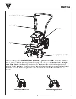
Page 8: ...drag bar This gives the Earthquakeâ Badgerä gear drive tiller its stability and its versatility For easy transport fold the wheels under the engine During operation the wheels unfold back and the drag bar folds down The long length between the tines and the drag bar make this the most comfortable front tine tiller on the market Transport Position Operating Position 3 way adjustable tine widths han...

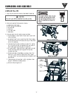
Page 9: ...row width assemble with short side of tine holder pipe towards center of machine d For wide width move left tine to right side and right to left side Assemble with long half of tine pipe towards machine e Slide top handle of handlebar over lower loop Put 5 16 18 x 1 3 4 bolts thru both holes from inside out put on 5 16 spring lockwashers and tighten with hand knobs f Check upper and lower jam nuts...

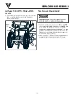
Page 10: ...y detergent oil Container must be marked A P I Service SF SJ Use no special additives with recommended oils Do not mix oil with gasoline Oil level must be full Check the oil level by removing the oil fill plug Oil level should be up to the bottom of the fill plug opening 2 Always check oil level before starting engine Refer to engine manual for capacity and type of oil to use depth regulator lever...

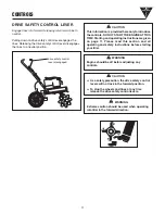
Page 11: ... the controls DO NOT START THE ENGINE AT THIS TIME Starting and operating instructions are given on page 11 Please read this section and all operating and safety instructions before starting your tiller CAUTION Engine should be off before adjusting any controls WARNlNG v As a safety precaution the drive safety control levers will not lock in the forward position v To stop the wheels and tines at a...

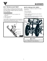
Page 12: ...ion BELT TENSION ADJUSTMENT Proper belt tension is critical to good performance After 1 2 hour of operation all cables may have to be adjusted due to initial stretch Thereafter check tension after every 2 hours of operation To increase belt tension 1 Loosen upper jam nut Turn nut up cable in 1 8 increments 2 Tighten lower jam nut 3 Check adjustment This procedure can be repeated until conduit adju...

Page 13: ...life of the motor as well as conserve fuel and reduce the noise level of the equipment Operating Speed For normal tilling set the throttle lever to fast Engine is shipped from factory without oil You must add engine oil before starting engine PRE START INSPECTION 1 Make sure all safety guards are in place and all nuts and bolts are secure 2 Check oil level in engine crankcase See your engine manua...

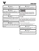
Page 14: ...150 F Avoid these areas Do not move choke control to CHOKE to stop engine Backfire or engine damage may occur To stop the engine at any time move throttle control to the off position To stop wheels and tines at any time release drive safety control levers to neutral position WARNING WARNING Engine and surrounding parts become extremely hot during normal use and will cause serious burn injuries if ...

Page 15: ...commended care operating intervals to extend the life of your unit EM See engine manual 1 Adjust throttle control after first 3 hours of operation or if engine is hard to start or run on occurs 2 Change oil after first 5 8 hours of use then after every 50 hours or every season Change oil every 25 hours when operating under heavy load or in high temperatures Maintenance Operation Check belt tension...

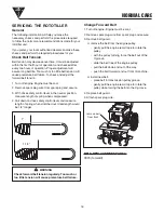
Page 16: ...sary checks and perform the procedures required to follow the normal care recommendations made for your rototiller unit If you prefer your local authorized dealer can make these checks and perform the required procedures for you Check Belt Tension Belt tension may decrease over time It must be adjusted within the first half hour of operation and checked after every two hours of operation Proper ad...

Page 17: ...th gasoline Oil level must be full Check the oil level by removing oil fill plug Oil level should be up to the bottom of the fill plug opening 2 Always check oil level before starting engine Refer to engine manual for capacity and type of oil to use Clean Tine Axle Shaft 1 Turn off engine Engine must be cool 2 Remove spark plug wire from spark plug and secure 3 Remove all vegetation string wire an...

Page 18: ...While engine is still warm drain the oil from the engine Refill with fresh oil of the recommended grade 5 Remove spark plug pour one half ounce of clean engine oil into cylinder Pull starter handle slowly several times to distribute oil Replace spark plug 6 Clean entire tiller 7 Store your tiller in a clean dry building STORAGE Do not store tiller in an non ventilated area where fuel fumes may rea...

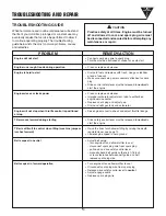
Page 19: ...ug Drive control safety lever must be released to neutral to start the engine Clean or replace air cleaner Improper carburetor adjustment take to authorized engine service center Replace spark plug and adjust gap Drain and refill gas tank and carburetor See engine manual to check and adjust throttle linkage Drive safety control lever must be released to neutral to start the engine Raise the tines ...

Page 20: ...ne Tension Spring Link 1 3262 Front Tine Drive Lever Welded 1 3264 Bottom Handle 1 3269 Top Handle 1 8655 Bolt Hex Hd 5 16 18 x 1 3 4 2 48406 Knob Five Star Black 5 16 18 2 53530 Spring Bee Hive Forward Cable Adjust 1 53606 Nut Nyloc 10 1 53607 Nut Jam 5 16 24 2 90138 Bolt Hex Hd 3 8 16 x 1 Grade 5 4 3100 3200 3365 Handlebar Assembly 3262 3261 90138 90138 3108A ...

Page 21: ...Shield 1 3305 Engine 6 5 hp Briggs 3365 1 3329 Tail Mount Upper 1 3330 Tail Mount Lower 1 3331 Wheel Shaft 1 2 1 3332 Tail Mount Hinge Shaft 1 2 1 3360 Idler Arm Forward 1 3364 Key Square 3 16 x 5 8 1 4361 Bolt Self Threading 3 8 16 x 1 1 2 3 8932 Nut Keps Toothed Washer 1 4 4 53194 Bolt Hex 3 8 24 x 1 Full Thrd Tec 1 53470 Washer 3 8 ID x 1 5 8 OD Tec 1 53596B Cable Yoke 1 63118 Bolt HHCS 1 4 20 ...

Page 22: ...y Half Moon 1 4 x 1 1 1810 Snap Ring External 2 3116 Gear Brass 1 ID 1 3122 Drive Shaft 1 3310TRAN Transmission Complete 1 3179 Pulley Single Groove Transmission 1 PART DESCRIPTION QTY 3196 Bolt Hx Hd 1 4 20 x 7 1 2 2 3205 Bearing Sealed 1 ID 2 3270 Snap Ring Eaton 3 4 1 3322 Tine Shaft 1 1 3323 Tine Set Outside Right 1 3324 Tine Set Inside 2 3326 Tine Set Outside Left 1 3364 Key 3 16 x 1 2 1 3370...

Page 23: ...____________________ ______________________________________________________________ ______________________________________________________________ ______________________________________________________________ ______________________________________________________________ ______________________________________________________________ ______________________________________________________________ _...

Page 24: ...Ardisam Inc 1690 Elm Street Cumberland Wisconsin 54829 715 822 2415 Fax 715 822 4180 1 800 345 6007 www ardisam com ...

Reviews: