background image

AVS-410CH-IM (10/13) 


Page 15 

Summary of Contents for AVS Series

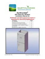
Page 1: ...ation Manual for R 410A SC and SD Compressor Units in Heat Cool or Cool Only Applications CONTENTS PAGE Pre Installation 3 Electrical Connections and Air Flow 4 AVS Dimensions and Electrical Ratings 6...

Page 2: ...manual Failure to provide installation and service by an authorized trained installer in a manner consistent with the subject manual will nullify the limited warranty coverage for the system READ THE...

Page 3: ...OR UNIT MODEL CAPCITY HEATER KW AVS 0024 CV R 410A VERTICAL 024 24 000 BTUH 5 AVS 0024 CH R 410A HORIZONTAL AVS 0036 CV R 410A VERTICAL 036 36 000 BTUH 10 AVS 0036 CH R 410A HORIZONTAL AVS 0048 CV R 4...

Page 4: ...ure 1 Figure 5 AVS Series Air Handler Control Panel and Field Wiring The blower speeds can be adjusted by changing the jumper settings on the control board as appropriate Heat and Cool panels A is the...

Page 5: ...0 C A 1957 1919 1900 1871 1947 B 1576 1565 1547 1517 1487 C 1495 1482 1451 1432 1409 D 1411 1385 1372 1338 1311 AVS 0068 CV A 2393 2393 2393 2393 2388 B 2227 2227 2221 2221 2221 C 2012 2012 2005 2005...

Page 6: ...AVS 410CH IM 10 13 Page 6 AVS Dimensions and Electrical Ratings...

Page 7: ...ngs Thermal Bulb and Field Conversion The air handler is shipped from ETI as it was ordered either for vertical or horizontal installation Figure 8 illustrates an air handler shipped from the factory...

Page 8: ...tension of this suction tube with options for the suction tube extension illustrated in Figure 9 This shows the suction tube directional options for an air handler that is to be installed in the VERTI...

Page 9: ...locating the thermal bulb on the suction line extension It shall be located at least 6 inches downstream of any fitting or bend in the suction tube extension and at the 3 00 4 00 8 00 or 9 00 o clock...

Page 10: ...hermal bulb firmly against the clean suction tube extension and parallel to it as shown in Figure 11 to ensure good thermal contact along the entire length of the thermal bulb Figure 11 Clamp the Ther...

Page 11: ...tension must be re located so the thermal bulb is on a HORIZONTAL section of the suction line extension as shown in Figures 10 and 11 with the thermal bulb located in the 3 00 4 00 8 00 or 9 00 o cloc...

Page 12: ...AVS 410CH IM 10 13 Page 12 Figure 13 Typical Air Handler Cased Coil After Conversion...

Page 13: ...MODEL TXV SERVICE PART NO 024 24 000 BTUH AVS 0024 C TXV 024C 036 36 000 BTUH AVS 0036 C TXV 036C 048 48 000 BTUH AVS 0048 C TXV 048C 060 60 000 BTUH AVS 0060 C TXV 060C 068 68 000 BTUH AVS 0068 CV TX...

Page 14: ...AVS 410CH IM 10 13 Page 14...

Page 15: ...AVS 410CH IM 10 13 Page 15...

Page 16: ...AVS 410CH IM 10 13 Page 16...

Page 17: ...AVS 410CH IM 10 13 Page 17...

Page 18: ...AVS 410CH IM 10 13 Page 18...

Page 19: ...AVS 410CH IM 10 13 Page 19...

Page 20: ...AVS 410CH IM 10 13 Page 20...

Page 21: ...AVS 410CH IM 10 13 Page 21...

Reviews: