


17
AVI Slide Rev - C
Master / Sla
ve
Setup
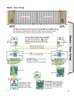
Master / Slave Setup
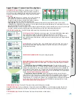
IMPORTANT:
The 120 VAC power for the master and slave operators
MUST
be on the
SAME
circuit breaker.
It is recommended that each gate operator’s initial set-up is completed (Direction of gate travel, limit nuts,
ERD reverse sensor and feature selector switches #1 - #4) before connecting the operators together.
After each operator functions individually, proceed to Master/Slave connection and operation.
Connect Master and Slave Operators Together
Choose your board type (Master or Slave) and use 20
GA stranded wire. Correct polarity is
VERY
important.
DO NOT
cross polarity. Operators will
NOT
function
properly if not wired correctly. Make sure to use color
coated wire.
Use the Close Timer (Feature
Selector #4 ON) on the master
board
ONLY
to set the gates
closing time 1 - 60 seconds.
Clockwise increases close time.
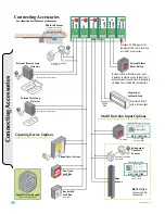
ACCESSORIES NOTE:
Connect accessories to
the master or slave boards).
See page 16 for accessory wiring connections.
M/S PHASE NOTE:
If the Master and Slave
operators are
NOT communicating properly
,
verify that they are on the same phase by
switching the M/S Phase jumper on either
the master or the slave unit. Make sure to
reset both boards.
Master Operator
Master Board
Slave Board
Slave Operator
Slave
Operator
Master
Operator
Negative to Negative 20 AWG Wire
Positive to Positive 20 AWG Wire
SLAVE MASTER
+ –
+ –
#9
#8
COMM PORT
COMM PORT
SLAVE MASTER
+ –
+ –
#9
#8
COMM PORT
COMM PORT
FEATURE SELECTOR
MASTER
OPEN RIGHT
BRAKE ON
CLOSE TIMER ON
SLAVE
OPEN LEFT
BRAKE OFF
CLOSE TIMER OFF
1
ON
234
OFF—ON
SELECT
O
FEATURE SELECTOR
MASTER
OPEN RIGHT
BRAKE ON
CLOSE TIMER ON
SLAVE
OPEN LEFT
BRAKE OFF
CLOSE TIMER OFF
1
ON
234
OFF—ON
SELECT
NOTE:
#1 & #2 switch settings are
based on the illustration above.
TIMER
MIN
MAX
MASTER
Operator
SLAVE
Operator
Opens to the Left
Opens to the Right
MOTOR 15A
GATE STATUS
FEATURE SELECTOR
M/S PHASE
1
0
CLOSING
CLOSE TIMER OFF
1
ON
2
3
4
OFF—ON
SELECT
MIN
MAX
OPEN
LIMIT
ERD OVERLOAD
OPENING CLOSING CLOSED
LIMIT
REVERSE
#2
GND
GND
RCVR
RECEIVER
ERD
M/P
POWER
MOTOR 15A
OPENING
TIMER
ERD CONTROL
MULTI FUNCTION
GATE STATUS
FEATURE SELECTOR
M/S PHASE
1
0
CLOSING
MASTER
OPEN RIGHT
BRAKE ON
CLOSE TIMER ON
SLAVE
OPEN LEFT
BRAKE OFF
CLOSE TIMER OFF
1
ON
2
3
4
OFF—ON
SELECT
MIN
MAX
OPEN
LIMIT
ERD OVERLOAD
OPENING CLOSING CLOSED
LIMIT
SLAVE MASTER
+ –
+ –
#9
#8
+ MAGLOCK
- 24 VDC
#5
+ ALARM
- 12 VDC
#6
REVERSE
LOOP
#2
POWER
24V
AC
#7
KEY
#3
M-FCN
#4
GND
GND
RCVR
24VAC
#1
COMM PORT
INPUT/OUTPUT
RECEIVER
ERD
M/P
RESET
1
O
N
2
ON ON STOP N/C
ON OFF CLOSE
OFF ON PHANTOM
OFF OFF EDGE SENSOR
S1 S2 FCN
COMM PORT
POWER
R
GHT
N
OP
R
Switch #1 MUST be ON.
Refer to
page 11 for more information
about each of the features.
Close Timer
(Master Operator)
Switch #1 MUST be OFF.
Switch #4
MUST
be
OFF.
Refer to
page 11 for more information
about each of the features.
POWERED BY EAGLE
AVI
POWERED BY EAGLE
AVI
M/S PHASE
1
0
EATURE SELECTO
MASTER
OPEN RIGHT
BRAKE ON
CLOSE TIMER ON
SLAVE
OPEN LEFT
BRAKE OFF
CLOSE TIMER OFF
1
O
N
2
3
4
OFF—ON
SELECT
Jumper
Summary of Contents for AVI
Page 2: ...2 AVI Slide Rev C ...
Page 23: ...21 AVI Slide Rev C NOTES ...


