Copyright 2013 Eagle Tree Systems, LLC Page 3
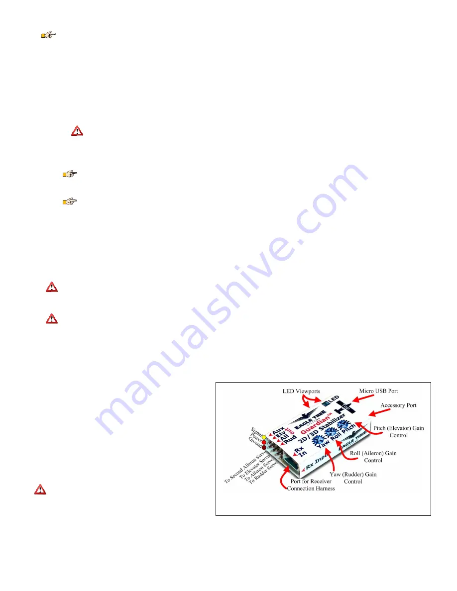
Figure 1 – Guardian Connections and Controls
•
To reduce the possibility of extreme servo deflection, it is recommended that you disable stabilization during initial setup. There are 3 ways to disable
stabilization:
o
If you are using a 3 position Mode/Config switch, move it to the center (disabled) position.
The Guardian’s LED should be OFF when in the Mode/Config switch is in the disabled position.
o
If you are controlling overall Guardian gain with a knob on your transmitter, set your Gain dial to -100% servo deflection (~1.1ms pulse length) to disable
stabilization.
o
If neither of these methods is applicable, turn the Pitch/Roll/Yaw dials on the Guardian to their centered position, which will also disable stabilization.
•
Configure your Guardian and transmitter for your wing type (see the Wing Type Configuration section for more information):
o
Turn off Elevon and V-Tail mixing in your transmitter, if it is enabled. Elevon and V-Tail mixing will be done by the Guardian.
o
By default, the Guardian is programmed for traditional wing types (mixing disabled). If your model requires elevon or V-Tail mixing, you can quickly
enable this feature by doing the following:
Within 15 seconds of powering on, toggle your Mode/Config switch three times, which is the Toggle Elevon Mixing switch gesture (move the
switch up-down-up-down-up-down if the switch is presently down, or down-up-down-up-down-up if the switch is presently up).
Your servos should “twitch” three times to indicate that you have toggled elevon mixing ON/OFF.
Move your control sticks to ensure that the mixing is now enabled. If not, you may need to re-run the Enable Elevon Mixing step.
Configuring the wing type correctly is critical! The model will not be controllable in the air if the wing type is incorrect.
•
Place your plane on a test bench so its orientation is the same as it would be during straight and level flight.
•
Reset your Trims and Level Flight Orientation:
o
Within 15 seconds of powering on, and with your plane still in the orientation of level flight, toggle your Mode/Config switch once, which is the Reset
Level Flight and Trims switch gesture. Your servos should “twitch” once to indicate that you have reset your controller trims and level flight orientation.
Any time you re-trim your plane or re-mount the Guardian, you will need to do this again to ensure best stabilization performance.
•
Compensate for servo directions and throws:
o
Set your Mode/Config switch to -100% (switch position 2 on a Spektrum
TM
controller). This activates “2D Mode”.
The Guardian’s LED should be blinking on and off repeatedly, which indicates 2D Mode.
o
Turn up the Overall Gain knob on your transmitter its center position (100% overall stabilization gain) if you are using the gain knob.
o
Observe how your servos react as you pitch, roll and yaw your plane.
o
Adjust the Guardian Pitch, Roll and Yaw axis dials with a screwdriver, so the servo for each axis deflects in the correct direction to bring your model back
to level. A centered dial asserts zero stabilization on that axis. Turning it clockwise or counterclockwise increases the gain and selects the servo
stabilization direction. See Figure 6 to see which directions your surfaces should move as you move your model.
•
Ensure your Transmitter’s elevator and aileron endpoints are set for +/-100%, if applicable.
The Guardian expects full ranges when it interprets your command
stick deflections to determine the desired orientation in 2D Mode.
•
Preflight:
o
Check that when you pitch, roll and yaw your plane while in either 2D or 3D Mode, that your servos oppose your movements. See Figure 6 in the
Preflight Checks section for more information.
If the control surfaces are not correctly set up to move in the appropriate directions to counteract pitch, roll and yaw movements, it could result
in a crash!
o
Do an engine run-up and confirm that the control surfaces are not moving around randomly due to excessive vibration or a loosely mounted Guardian.
If the control surfaces are moving on their own during run-up, this could result in a crash! Do not fly if this is the case.
o
Range check your model!
Guardian Physical Connections/ Controls
Please refer to Figure 1. The Guardian has the following physical connections and controls:
•
Port for Receiver Connection Harness – this is where the included harness connects. The servo plugs on the harness then connect to the appropriate receiver channels.
Please see the Receiver Connection Harness section below for more
information.
•
Servo Connection Ports – connect the appropriate servos to the
Guardian here, noting the plug orientation in Figure 1. Please see the
Wing Hookup Configurations section below for more information.
•
Yaw, Roll and Pitch gain control dials – these dials set the individual
gains for the Yaw (Rudder), Roll (Aileron) and Pitch (Elevator) axes, as
well as setting the direction of stabilizing servo travel, and are adjusted
with a small screwdriver. Please see the Tuning Stabilization Gains
section for more information.
•
Micro USB port – this port accepts a “Micro B” USB cable (not
included). Connection to a PC lets you update the Guardian firmware,
and also configure and tune your Guardian via your PC. Please see the
PC User Interface section for more information.
Do not apply upward force on the USB connector when a
cable is inserted! Doing so can damage it.
•
Accessory (Data) Port – this port is for future expansion, and is not used
presently. Please let us know how we should use this port!
•
LED Viewports – for your convenience, the status LED can be seen from both the top and side of the Guardian case. Please see the Status LED section for more
information.


