BMS-icom Installation Manual
8
Step 3: Sensing Cable Connection
Parts:
Clamps, clamp covers, voltage sensing cables, current sensing cables
Tools:
Phillips screwdriver, 2-3mm flathead, duct, duct tape, cable ties/zip ties, wire cutter,
wire stripper (22 AWG)
(1) Connection Order
There are two sensing cables, voltage and current, which connect to the clamps. Each cable
has a number of sensing leads which are color coded to help with installation. The connection
order for the sensing cable leads is:
Connection of Vs & Is Leads
Connection
Voltage
Current
Clamp 1
Grey
Black
Battery 1
Clamp 2
Green
Battery 2
Clamp 3
Blue
Red
Battery 3
Clamp 4
Orange
Battery 4
Clamp 5
Brown
White
NOTE:
Total sensing cable length should be as short as possible to decrease noise, if cable
length is longer than needed, shorten its length (see step 2)
WARNING:
Do not plug connectors for any cable into BMS icom until all sensing leads have
been connected to the clamps on the battery string
(2) Connect Sensing Leads to Clamps
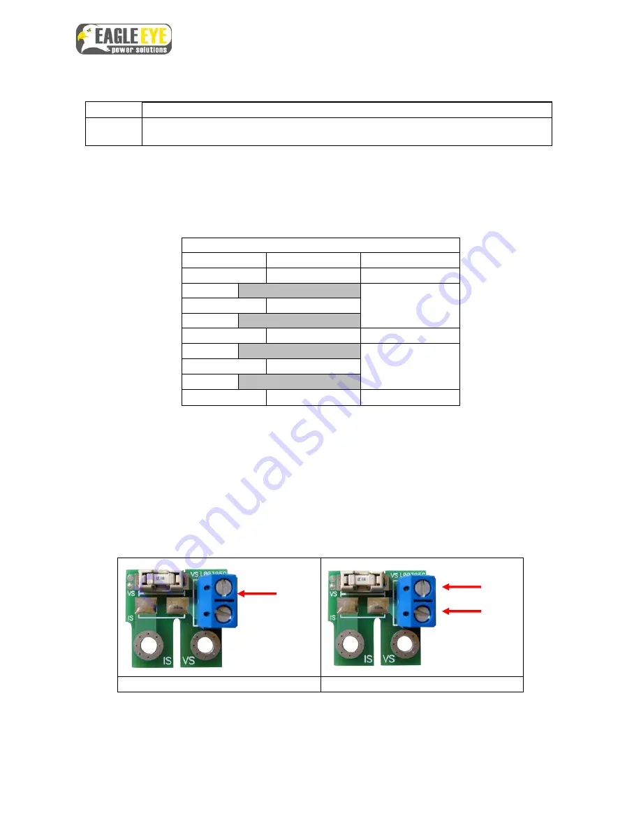
1. Observe carefully which slot on the board is used for each cable.
Voltage Board
Current Board
2. Insert the end of the sensing lead into the correct slot following the sequence in the
“Connection of Vs & Is Leads” table above
3. Using a 2-3mm flathead driver, tighten the screw down all the way until you can
firmly pull on the sensing lead without it coming out
4. Place protective covers over the clamps
Vs
Vs
Is


